
A gearbox housing can look simple from the outside, but hidden casting defects, poor datum control, or weak inspection can cause serious problems after assembly.
Gearbox housings are commonly made from cast iron, ductile iron, aluminum alloys, or cast steel. The housing is first formed by casting, then critical datums, bearing bores, mounting faces, threaded holes, and sealing surfaces are precision machined and inspected.
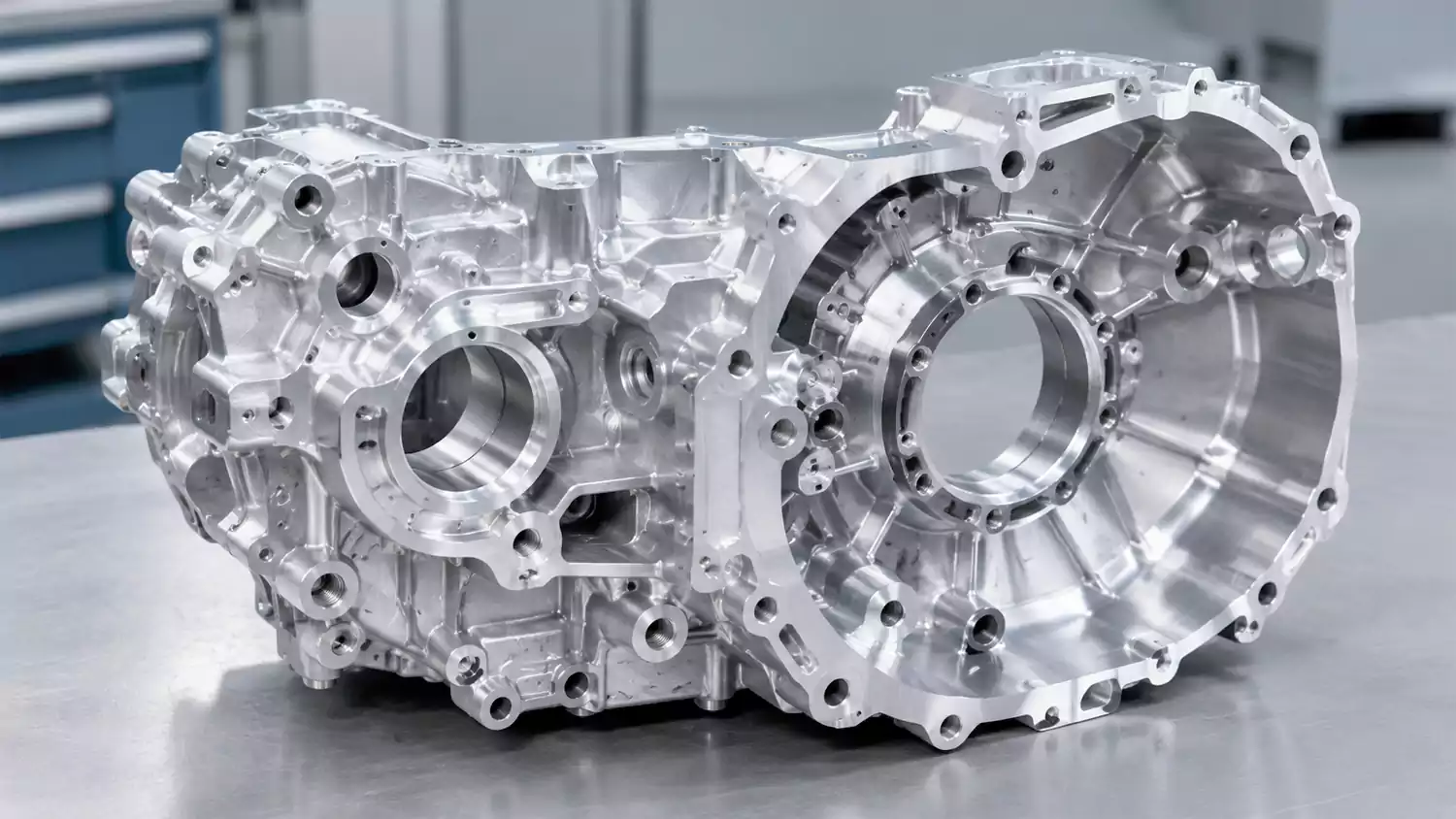
A gearbox housing has to carry gears, shafts, bearings, seals, and other components in the correct position. I always look at the housing as a complete mechanical system, not just as a machined metal shell. The material, casting quality, machining sequence, and inspection method all affect the final gearbox.
What Materials and Manufacturing Processes Are Used for Gearbox Housings?
A wrong material or poor casting can create problems that CNC machining cannot fix. I have seen parts with excellent dimensional accuracy fail because the material structure or internal casting quality was not good enough.
I select gearbox housing materials based on load, vibration, weight, thermal conditions, corrosion requirements, machinability, and production volume. Common choices include gray cast iron, ductile iron, aluminum alloys, and cast steel.
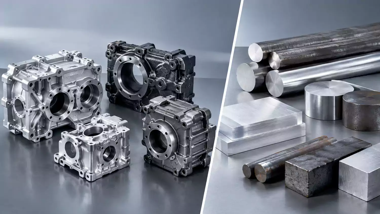
For many industrial gearboxes, gray cast iron is a practical choice because it provides good vibration damping, dimensional stability, and machinability. Ductile iron is useful when the housing needs higher mechanical strength and impact resistance. Aluminum alloys can reduce weight and work well where low mass and good machinability are important. Cast steel can be considered when the housing must handle higher mechanical loads.
I usually start with the working conditions rather than the material price. I need to know the gearbox load, operating speed, temperature, vibration level, expected service life, and surrounding environment. I also check whether the housing has thin walls, large bearing pockets, deep cavities, or complex mounting structures.
The manufacturing route normally starts with casting when the housing has a large and complex shape. The casting produces the main external geometry, internal cavities, ribs, bosses, and mounting structures. After casting, I allow the material to stabilize before precision machining when the application requires tight dimensional control.
The machining process then establishes the important datums. I normally machine the main mounting face first when it is the correct reference surface. I then use that datum to control bearing bores, shaft locations, bolt holes, sealing surfaces, and other critical features.
| Material | Typical reason for selection | Main consideration |
|---|---|---|
| Gray cast iron | Vibration damping and machinability | Weight and impact strength |
| Ductile iron | Higher strength and toughness | Machining and material condition |
| Aluminum alloy | Low weight and good machinability | Stiffness and thermal expansion |
| Cast steel | High mechanical load capability | Cost and machining difficulty |
The most important point is that I do not treat casting and machining as two separate quality problems. They are connected. A machining center can produce a bore within tolerance, but it cannot remove internal porosity, shrinkage cavities, cracks, or poor metallurgical structure outside the machined area.1
For this reason, I always put material and casting quality ahead of machining speed. Quality always comes before price.
Which Gearbox Housing Features Require Precision CNC Machining?
Not every surface on a gearbox housing needs the same tolerance. I focus machining time and inspection effort on the features that control assembly, gear alignment, sealing, and load transfer.
The most important CNC-machined gearbox housing features usually include bearing bores, shaft alignment surfaces, mounting faces, sealing surfaces, locating holes, threaded holes, and precision dowel holes. These features directly affect gearbox assembly and operating stability.
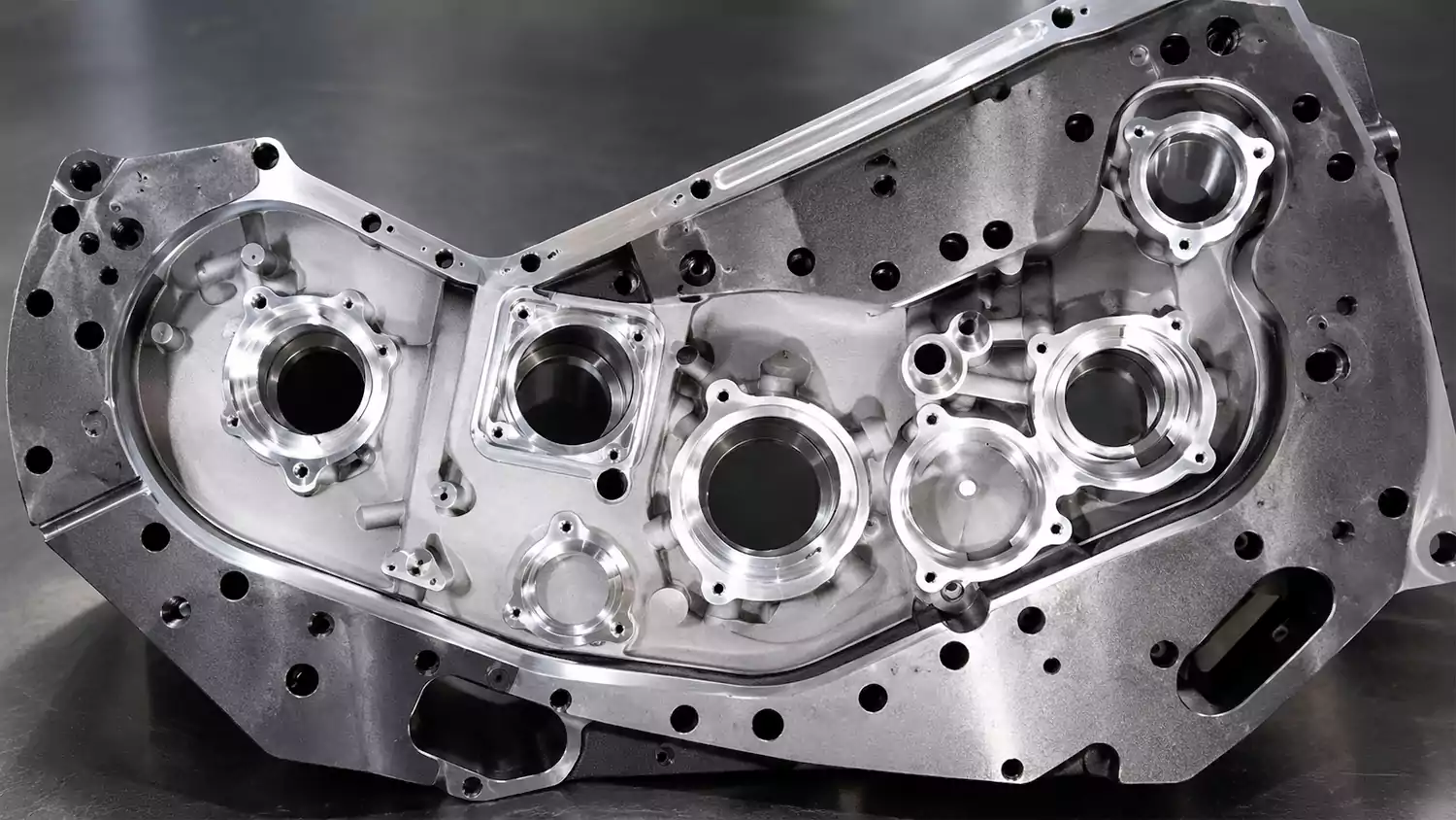
The bearing bores are usually among the most important features. Their diameter, roundness, position, and relationship to other bores affect shaft alignment. If two bearing seats are not correctly aligned, the shaft can experience unwanted loading. That can increase noise, heat, and bearing wear.
The mounting surfaces are also important. I use them as primary datums when the drawing defines them as the main reference. A poor mounting surface can transfer errors to other machined features.
I pay special attention to the relationship between features, not just the individual tolerance of each feature. A bearing bore may be within its diameter tolerance, but its true position can still be wrong. A mounting hole may also be correctly sized but incorrectly located relative to the bearing centerline.
Sealing surfaces require another type of control. Surface finish, flatness, and local deformation can affect gasket performance or sealant application. If the housing contains oil, even a small problem around a sealing interface can become a production or service issue.
Threaded holes and dowel holes also deserve careful control. Dowel holes normally provide more accurate locating than standard clearance holes. I machine them from controlled datums and inspect their position relative to the main gearbox reference features.
I also consider the machining sequence. A large gearbox housing can move slightly when material is removed. If I machine thin sections too aggressively or remove large amounts of material without a stable setup, the part can lose its intended geometry.
For complex housings, I prefer to reduce the number of setups when the machine and workholding allow it. A 4-axis or 5-axis machining center can sometimes maintain relationships between features more effectively than repeated manual repositioning.
The exact tolerance always comes from the customer's drawing and functional requirements. I do not apply an unnecessarily tight tolerance to every feature. That can increase machining time and inspection cost without improving gearbox performance.
How Is a Precision Gearbox Housing Manufactured and Inspected?
A gearbox housing needs a controlled process from raw material to final inspection. I do not consider the part finished when the CNC machine stops. The inspection process has to confirm that the machined geometry matches the design intent.
A precision gearbox housing is typically manufactured through casting, material inspection, datum machining, rough machining, stress stabilization when required, finish CNC machining, deburring, cleaning, and final dimensional inspection. Critical bores and positional relationships should receive special inspection attention.
My machining sequence normally starts with identifying the primary datum. I establish that surface first and then build the remaining machining operations around it. This gives me a stable reference for the features that control gearbox assembly.
I also separate rough machining from finish machining when the part requires it. Rough machining removes most of the material. Finish machining then produces the final dimensions and surface conditions. This approach reduces the chance that heavy cutting forces will affect the final geometry.2
For a gearbox housing, I normally pay particular attention to:
- Bearing bore diameter and roundness
- Bore-to-bore center distance
- Bore position relative to mounting datums
- Mounting face flatness
- Dowel hole position
- Thread dimensions
- Sealing surface condition
- Overall housing dimensions
- Wall thickness where specified
- Casting defects in critical areas
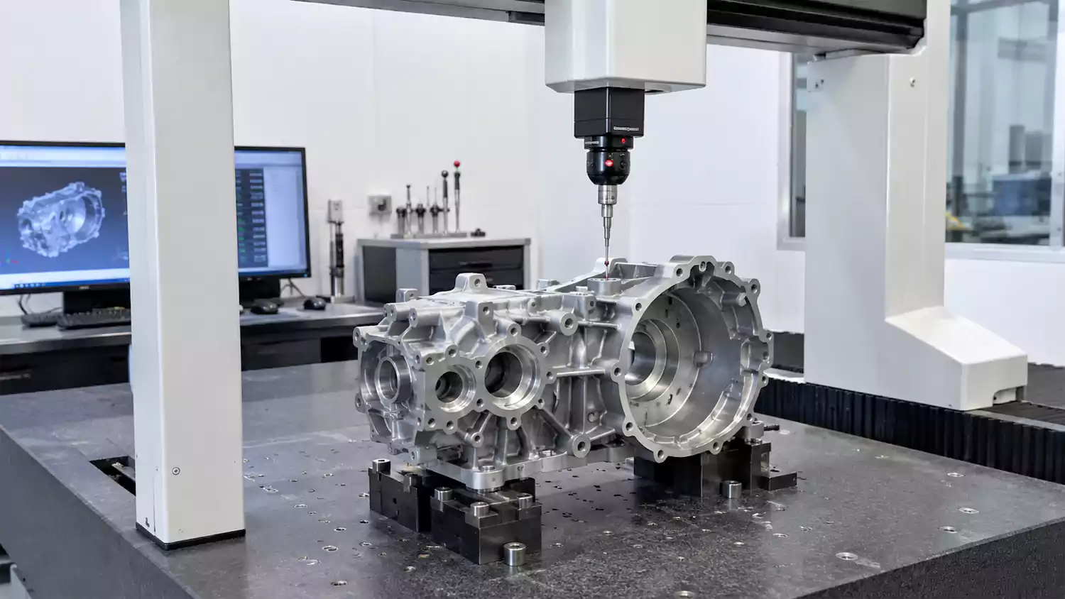
A CMM can be useful for checking the relationship between multiple features. For simpler dimensions, I may use bore gauges, micrometers, height gauges, calipers, and other appropriate inspection tools. The inspection equipment should match the tolerance and function of the feature.
A Practical Gearbox Housing Example
I once worked on a gearbox housing where the customer needed consistent positioning between the main bearing bores and the mounting datum. The housing was not extremely small, so the challenge was maintaining the geometric relationship after machining.
The production target was similar to the following:
| Parameter | Production requirement |
|---|---|
| Housing material | Ductile iron |
| Main bearing bore | Ø80 mm |
| Bore diameter tolerance | ±0.015 mm |
| Bore center distance | 210 mm |
| Center distance tolerance | ±0.025 mm |
| Mounting face flatness | 0.03 mm |
| Dowel hole position | ±0.02 mm |
| Production quantity | 500 pcs |
| Inspection method | CMM + dedicated gauges |
I did not start by trying to achieve the tightest bore tolerance immediately. I first checked the casting condition and established the primary datum. Then I rough-machined the major surfaces and allowed the housing to stabilize before the final machining operation.
During final machining, I controlled the bearing bores from the same reference system.3 This was important because the customer cared about shaft alignment more than the absolute accuracy of any single external dimension.
The inspection process also focused on feature relationships. I checked the bore diameter, bore position, center distance, mounting face, and locating holes. This helped us identify whether an error came from the tool, fixture, datum, or material movement.
This is the part of gearbox housing manufacturing that I think is often underestimated. A housing can have many dimensions that look correct on an inspection sheet. The real question is whether the important features have the correct relationship to each other.
For me, that is what precision machining really means.
What Should You Consider When Sourcing a Gearbox Housing Manufacturer?
A low quote means little if the housing has casting defects, poor alignment, or inconsistent dimensions. I focus on whether the supplier can control the complete process.
When sourcing a gearbox housing manufacturer, I focus on four things: material and casting quality, CNC machining capability, precision inspection, and consistent production quality.

I first check how the supplier controls the material and casting process. Good machining cannot compensate for poor casting quality. The supplier should understand the material specification and identify critical areas where internal defects could affect performance.
I then check the CNC machining process. I want to know how the supplier establishes datums, controls bearing bores, manages multiple setups, and maintains the relationship between critical features.
Inspection capability is also important. The supplier should have suitable measuring equipment for the required tolerances. For complex gearbox housings, CMM inspection can help verify bore positions, center distances, mounting surfaces, and other critical relationships.
Finally, I look at production consistency. A supplier may produce one good prototype, but production orders require stable fixtures, repeatable machining processes, controlled inspection, and experienced operators.
I also recommend providing complete technical information during the quotation stage. The supplier should receive the 3D model, 2D drawing, material specification, surface treatment requirements, tolerance requirements, quantity, and inspection requirements.
I have learned after more than 20 years in machining that the lowest price is not always the lowest total cost. Poor casting quality, machining errors, and inconsistent dimensions can create much higher costs later.
Conclusion
A reliable gearbox housing starts with sound material and casting quality, then depends on controlled CNC machining, correct datums, and inspection of the features that matter most to gearbox performance.
-
"What Casting Defects Does Hip Resolve In Heas? Eliminate ...", https://kinteksolution.com/faqs/what-casting-defects-does-hot-isostatic-pressing-hip-equipment-resolve-in-the-post-processing-of-high-entropy-alloys-heas. Machining can correct dimensional location and surface finish but does not eliminate subsurface defects such as casting porosity, shrinkage-related discontinuities, or internal cracks that originate during solidification; removing them requires processes that alter the bulk material (e.g., appropriate casting control, hot isostatic pressing, or redesign), so machining alone cannot guarantee defect removal beyond the cut zone. Evidence role: mechanism; source type: research. Supports: A machining center can produce a bore within tolerance, but it cannot remove internal porosity, shrinkage cavities, cracks, or poor metallurgical structure outside the machined area.. Scope note: Direct proof is context-dependent (depends on defect size, location relative to the cut depth, and whether post-processing is applied), but the general materials-science principle is that machining is a material-removal process and cannot address bulk casting defects outside the machined region. ↩
-
"Research Progress in Multidimensional Prediction of ... - PMC", https://pmc.ncbi.nlm.nih.gov/articles/PMC12898247/. A reference on machining dynamics or error generation in milling/turning should explain that separating roughing and finishing reduces distortion from cutting forces by allowing elastic/plastic deformation and residual stresses to settle before final cuts, improving form/size outcomes. Evidence role: mechanism; source type: paper. Supports: Separating rough machining from finish machining reduces the chance that heavy cutting forces will affect the final geometry.. Scope note: Support should describe the general cause-and-effect (cutting-force/deflection and deformation behavior) but may not quantify the effect for gearbox housing specifically. ↩
-
"Designing for Repeatability: Fixtures, Datums, and Process ...", https://www.allmetalsfab.com/designing-for-repeatability-fixtures-datums-and-process-control/. A manufacturing/fixturing or GD&T reference should explain that using a consistent datum/reference frame across operations reduces differential errors and helps maintain relationships such as bore position and center distance relative to mounting datums, consistent with datum-driven tolerancing practice. Evidence role: mechanism; source type: encyclopedia. Supports: Using the same reference system to control bearing bores during final machining is important for maintaining the functional alignment/relationships.. Scope note: A general fixturing/GD&T source may support the principle, but it may not prove the specific result achieved in the described case without process parameters or measurement outcomes. ↩