
A connecting rod can look simple from the outside, but it carries repeated loads between the piston and crankshaft. A weak material, poor blank, or unstable process can quickly become a serious engine problem.
I choose the connecting rod material and manufacturing process based on load, weight, geometry, fatigue requirements, and production volume. Forging is usually suitable for heavily loaded rods, while precision investment casting can support lightweight and complex designs. In both cases, blank quality comes first because CNC machining cannot repair internal casting or forging defects.
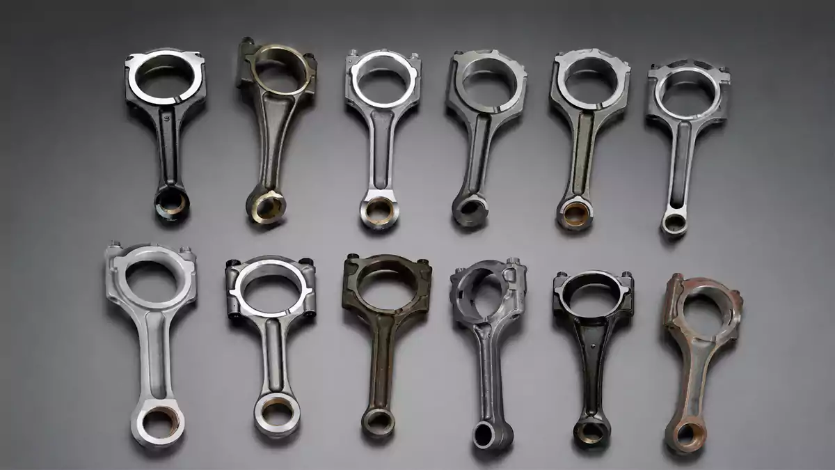
I have learned this point from years of working with metal parts: machining accuracy cannot compensate for poor material integrity. A CNC machine can produce a precise surface, but it cannot remove a hidden internal crack or repair a weak structure inside the blank. That is why I always look at the complete manufacturing route instead of judging a connecting rod only by its final dimensions.
Why Is the Connecting Rod Critical to Engine Performance and Reliability?
A connecting rod works under repeated tensile and compressive loads, and it must transfer these forces without excessive deformation, cracking, or fatigue damage. If I focus only on dimensional accuracy, I can miss the more important question of whether the rod can survive its actual working conditions.
I treat a connecting rod as a structural load-transfer component. Its material strength, fatigue resistance, geometry, surface condition, and manufacturing integrity all affect engine reliability.
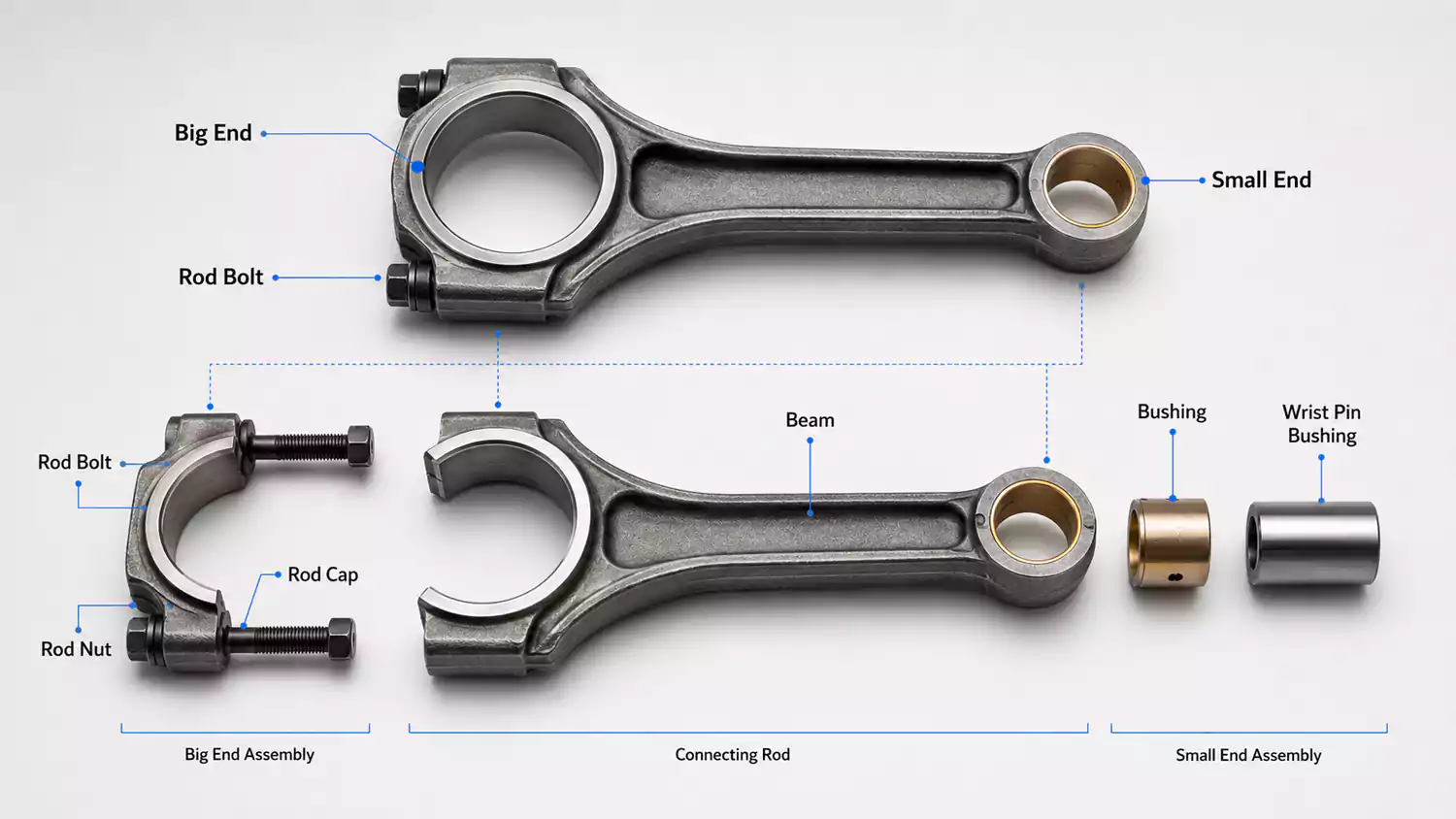
What loads does a connecting rod handle?
During engine operation, the connecting rod changes direction continuously. The piston moves up and down while the crankshaft rotates. This creates a combination of compression, tension, bending, and inertial loading.
The big end connects to the crankshaft, while the small end connects to the piston pin. The center section transfers the load between these two ends. I pay special attention to the transition areas because sudden changes in section thickness can increase local stress.
I also consider engine speed. As speed increases, inertial forces become more important.1 A heavier connecting rod can increase the forces created by reciprocating motion. This is one reason why engineers often try to reduce weight without weakening the rod.
Why does fatigue matter so much?
A connecting rod may experience millions of load cycles during its service life.2 The part does not need to fail under one unusually high load to become a problem. Small defects can grow under repeated loading.
For this reason, I look at more than tensile strength. Fatigue resistance, material consistency, grain structure, surface condition, and defect control are also important.
A supplier that can hold a tight machining tolerance but cannot control the raw blank is not enough for a critical connecting rod. The manufacturing process must protect the part from the beginning.
How Do You Choose the Right Material and Manufacturing Process for Custom Connecting Rods?
I select the process after I understand the load, geometry, weight target, material requirements, production quantity, and required machining accuracy. Heavy-duty applications often favor forging, while complex lightweight geometries can make precision investment casting attractive.
I choose forging for custom connecting rods when high mechanical loads and fatigue resistance are the main priorities. I consider precision investment casting when complex geometry, weight reduction, near-net shape, and material efficiency are more important.
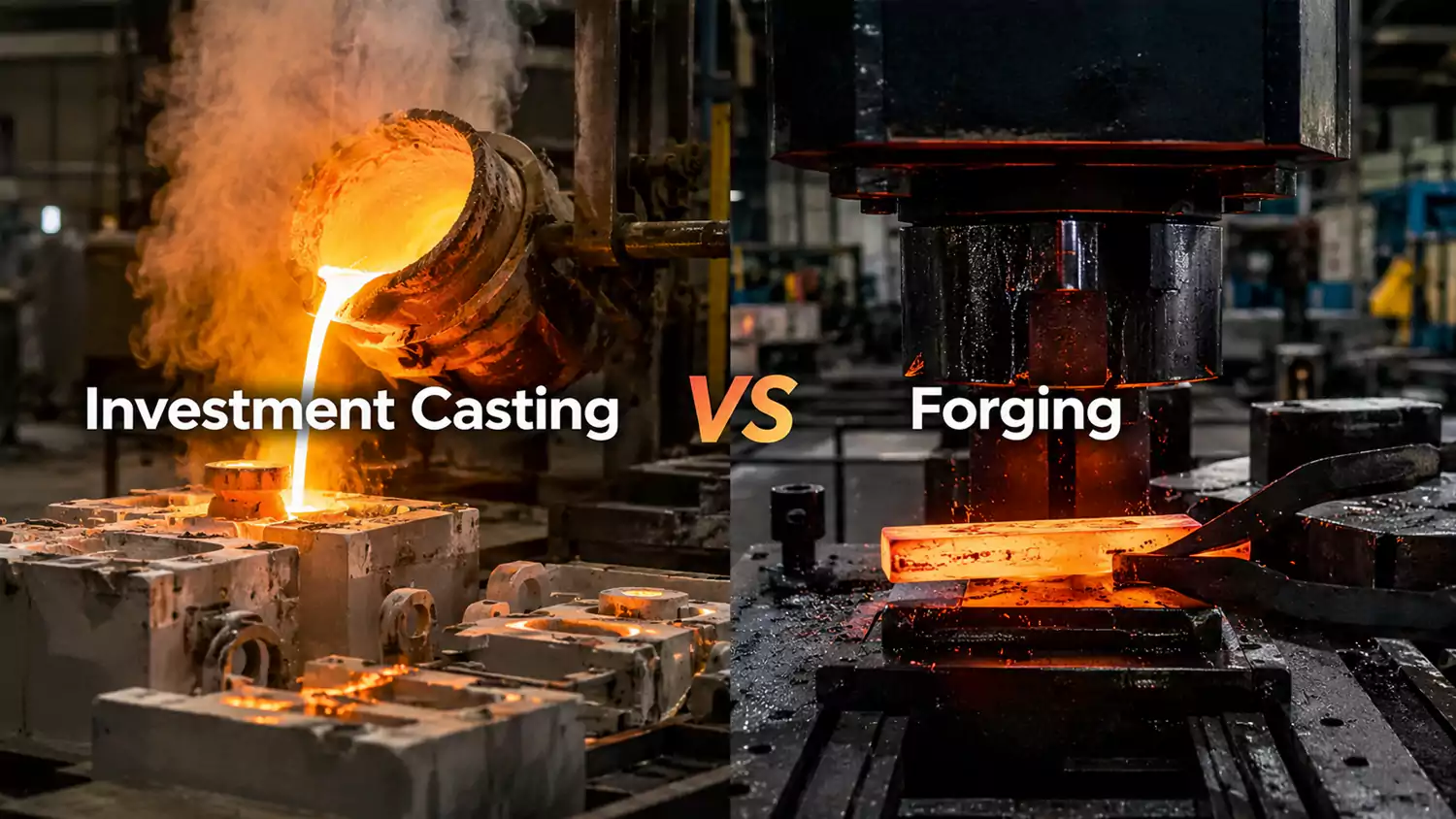
Forging for heavily loaded connecting rods
Forging is a strong option when the connecting rod must withstand high repeated loads. The process can produce a dense metal structure that is well suited to demanding mechanical applications.
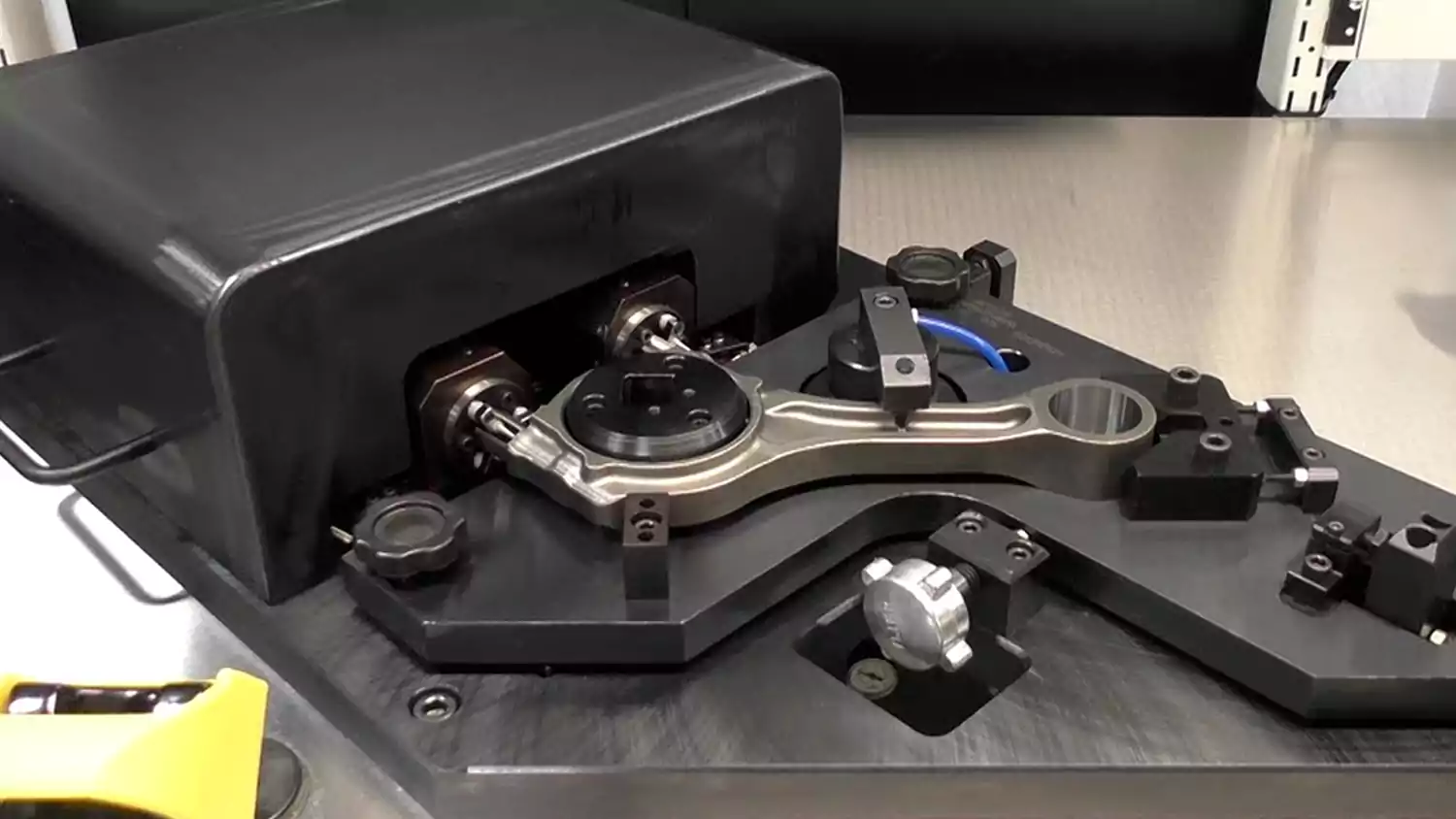
I normally expect forged rods to require machining after forming. Critical areas such as the crank bore, piston-pin bore, split surfaces, threaded features, and bearing locations may need accurate CNC machining.
The important point is that forging does not automatically mean perfect quality. The forging process still needs controlled temperature, deformation, die condition, trimming, heat treatment, and inspection. A poor forging blank can create problems that later machining cannot remove.
Precision investment casting for complex designs
Investment casting becomes attractive when the connecting rod has complex geometry or when the design benefits from a near-net-shape blank.
I can use investment casting to form details that would require more machining or multiple manufacturing operations in another process. This can help reduce material waste and machining time.
For lightweight designs, this flexibility can be useful. Engineers can also create more complex shapes while keeping the finished part within a controlled weight range.
But I never treat casting as a shortcut. Internal porosity, shrinkage, inclusions, cracks, or other defects can compromise a connecting rod even when the final machined dimensions look perfect.
An illustrative custom connecting rod case
I would use the following type of process evaluation when developing a custom connecting rod. The figures below are an illustrative engineering example, not a production specification for a particular engine.
| Parameter | Example Requirement |
|---|---|
| Finished length, center-to-center | 145 mm |
| Maximum finished width | 32 mm |
| Target finished mass | 420 g |
| Big-end bore | Ø52.000 mm |
| Small-end bore | Ø22.000 mm |
| Critical bore tolerance | ±0.010 mm |
| Main material option | 4340 alloy steel |
| Alternative process | Precision investment casting |
| Heat treatment target | Controlled hardened and tempered condition |
| Final inspection | CMM, bore measurement, visual and NDT checks |
For a high-load version, I would first evaluate a forged alloy-steel blank. I would check the forging direction, die fill, machining allowance, heat treatment, and fatigue-critical transitions. I would then machine the bores and other critical surfaces.
For a complex lightweight version, I would compare a precision investment casting route. I would focus on shell quality, filling behavior, feeding, internal defects, heat treatment, and radiographic or other suitable non-destructive inspection.
The most important lesson is not which process always wins. The correct choice depends on the engine and the actual design target. I would rather select a process that protects structural integrity than choose a process only because it gives the lowest initial machining cost.
For broader engine and powertrain requirements, I also consider the complete part system rather than treating the connecting rod as an isolated component. This is where experience with custom engine & powertrain parts solutions can become useful during material, process, and manufacturing planning.
Connecting Rod vs. Piston Rod and Other Similar Components
I often see different rod-shaped components confused during early sourcing discussions. Their names may look similar, but their functions and manufacturing requirements can be very different.
A connecting rod transfers reciprocating piston motion to a rotating crankshaft, while a piston rod normally transfers force between a piston and another mechanism. Their loads, interfaces, geometry, and manufacturing requirements are different, so they should not be specified or sourced as interchangeable components.
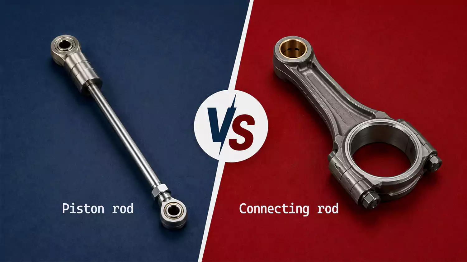
Connecting rod vs. piston rod
A connecting rod is designed around the relationship between the piston and crankshaft. It usually has two major ends and a central beam. The big end must interface accurately with the crankshaft, while the small end must locate correctly around the piston pin.
A piston rod has a different role. It commonly connects a piston to another mechanical component and is often associated with reciprocating cylinders or hydraulic and pneumatic systems.
I would not use the same sourcing criteria for both parts. A connecting rod may be dominated by fatigue loading and reciprocating inertia. A piston rod may place more emphasis on straightness, surface finish, sealing surfaces, corrosion resistance, and wear behavior.
Why geometry changes the manufacturing decision
The geometry of a connecting rod directly affects the process I choose. A simple forged shape may be economical for large production volumes. A more complex design may benefit from investment casting because the casting can approach the required geometry before machining.
I also consider how much material needs to be removed. If a supplier produces a near-net-shape blank, machining can focus on critical functional surfaces instead of removing large amounts of material.
This is where I connect casting and machining experience. I do not see CNC machining as an isolated operation. I see it as the final stage of a manufacturing chain that starts with material selection and blank production.
This same way of evaluating materials, processes, machining, and supplier capabilities applies across custom engine & powertrain parts, where each component needs to be matched to its actual operating requirements rather than selected from a generic manufacturing process.
How Do You Ensure Custom Connecting Rod Quality and Choose the Right Manufacturer?
I judge a connecting rod supplier by the entire process, not by the final inspection report alone. The supplier should be able to explain how the blank is produced, how defects are controlled, how heat treatment is managed, and how critical dimensions are verified.
I look for controlled material traceability, stable blank production, suitable heat treatment, accurate CNC machining, documented inspection, and clear communication. A reliable manufacturer should show how quality is built into the connecting rod manufacturing process rather than discovered only at final inspection.
Start with the blank, not the CNC machine
I have seen a common mistake in custom part sourcing. A buyer spends a lot of time discussing CNC tolerances while giving little attention to the blank.
That order should be reversed.
If the blank contains a serious internal defect, machining cannot make the material structurally sound. CNC machining can remove surface material and create accurate features. It cannot repair internal shrinkage, porosity, inclusions, or cracks hidden below the machined surface.
This is especially important for investment-cast connecting rods. I would ask how the foundry controls wax patterns, ceramic shells, melting, pouring, feeding, solidification, heat treatment, and non-destructive inspection.
For forged rods, I would ask about forging temperature, die filling, grain flow, trimming, heat treatment, and defect inspection.
Check the critical dimensions
Connecting rod bores deserve particular attention because they directly affect the relationship between the rod, bearing, crankshaft, and piston pin.
I would normally ask the supplier to identify critical characteristics before production starts. These may include:
| Quality Item | Why I Check It |
|---|---|
| Big-end bore diameter | Controls bearing and crankshaft fit |
| Small-end bore diameter | Controls piston-pin fit |
| Center-to-center distance | Controls engine geometry |
| Bore alignment | Prevents unwanted loading |
| Rod weight | Affects reciprocating balance |
| Surface roughness | Supports proper interface performance |
| Material condition | Supports required mechanical performance |
| Internal integrity | Reduces risk of fatigue-related failure |
| Heat treatment | Controls mechanical properties |
| Traceability | Connects finished parts to production records |
What should I ask a potential supplier?
I want direct answers before I approve a supplier. I would ask whether the company can provide material certificates, process records, heat-treatment documentation, dimensional inspection reports, and suitable non-destructive testing.
I would also ask for evidence that the supplier understands the difference between casting quality and machining quality.
A good manufacturer should be able to explain where the main risks exist in the process. I value that explanation more than a simple statement that the factory has modern CNC equipment.
When I evaluate a custom connecting rod supplier, I also consider whether the company can support both development and production. A supplier may need to modify tooling, adjust machining fixtures, change machining allowances, or refine inspection methods during development.
I prefer a manufacturer that can discuss these issues openly. That usually tells me whether the supplier understands the part or is simply quoting a drawing.
Conclusion
A reliable custom connecting rod starts with the right material, manufacturing process, and blank quality. I match forging or precision investment casting to the required load, geometry, weight, and production goals, then control heat treatment, CNC machining, and inspection around the finished part’s critical requirements.
If you are developing a custom connecting rod or another engine component, I recommend defining these requirements with your manufacturing partner before production begins.
-
"Dynamic analysis and controller design for a slider–crank ...", https://www.sciencedirect.com/science/article/pii/S228843001630032X. In reciprocating mechanisms, the inertia of the reciprocating mass produces additional cyclic (dynamic) loads on the connecting rod that scale with engine speed (often expressed through angular velocity terms), so higher rotational speed increases the magnitude of inertial loading compared with static components. Evidence role: mechanism; source type: research. Supports: As speed increases, inertial forces become more important.. Scope note: Scaling laws depend on the specific kinematics/geometry and whether the comparison is to mean/static loads versus acceleration components; sources typically describe qualitative and/or model-based trends rather than a single universal formula. ↩
-
"[PDF] Fatigue Analysis of Engine Connecting Rod Based on Finite ...", https://www.atlantis-press.com/article/25898813.pdf. Connecting-rod fatigue design commonly treats service life in terms of the number of stress cycles (often estimated from duty cycle and operating time), and guidance for fatigue life assessment uses cycle-counting methods that can correspond to very large numbers of loading cycles over typical engine service intervals. Evidence role: general_support; source type: institution. Supports: A connecting rod may experience millions of load cycles during its service life.. Scope note: “Millions of cycles” depends on engine type, speed/load history, and assumed damage model; most sources support the plausibility via cycle-counting methods rather than a single universal number. ↩