
Engine mount brackets look simple, but they carry a difficult job. They must support the engine while absorbing vibration, repeated loads, and temperature changes.
I treat an engine mount bracket as a structural component, not just a shaped metal part. A reliable bracket needs the right material, sound casting or forging, accurate machining, and validation against static load, vibration, and thermal fatigue before production.
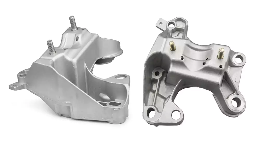
I have seen engine mount brackets fail for reasons that were not obvious from a drawing. A bracket can pass a basic dimensional inspection and still develop cracks after repeated vibration. That is why I look at the whole manufacturing process, from material and casting design to machining and final inspection.
Why Are Custom Engine Mount Brackets So Important?
A bracket can look strong on the drawing and still fail in service. If vibration, load paths, or thermal expansion are ignored, the problem often appears only after the part reaches the vehicle.
Custom engine mount brackets are important because they transfer engine loads and vibration into the vehicle structure while maintaining the required position of the powertrain. Their geometry, material, stiffness, and mounting accuracy directly affect durability, noise, vibration, and long-term reliability.
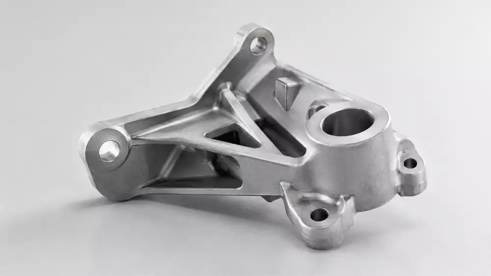
When I review an engine mount bracket, I first look at how the load moves through the part. The mounting bosses and ribs cannot be treated as separate features. They work together as one structure. A weak transition between a rib and a boss can create a stress concentration. A thin wall can distort during casting or machining. A mounting hole that is slightly out of position can also make installation difficult.
Static load is only the starting point. A good bracket has to survive vibration and thermal fatigue. I run both checks on every design. If it does not pass, I do not touch the mold.
For automotive applications, I normally pay close attention to four areas:
| Design factor | What I check |
|---|---|
| Load path | How engine forces move from the mount into the vehicle structure1 |
| Rib structure | Whether ribs provide stiffness without creating excessive casting stress |
| Mounting bosses | Wall thickness, fillets, hole position, and local strength |
| Thermal behavior | Expansion, contraction, and fatigue around high-stress areas |
I also look at the installation environment. An engine mount bracket may sit close to the engine, transmission, exhaust system, or other heat-producing components. The bracket may experience temperature cycles every time the vehicle starts, operates, and cools down.
This is why I prefer to validate the design before committing to tooling. If the basic structure is wrong, machining cannot repair it. CNC machining can make a hole accurate, but it cannot fix a poor load path or an undersized structural section.
How Do You Choose the Right Material for an Engine Mount Bracket?
Material selection affects bracket strength, weight, corrosion resistance, thermal behavior, castability, and machining cost. I choose the alloy based on the complete operating environment instead of selecting it only by tensile strength.
I choose the right engine mount bracket material by comparing strength, fatigue performance, weight, thermal behavior, corrosion resistance, castability, and machinability against the bracket's actual load and operating environment.
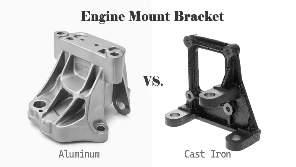
For lightweight automotive structures, aluminum alloys are often attractive because they provide a good strength-to-weight ratio and can reduce vehicle mass. Aluminum also works well when the bracket requires complex ribs, bosses, and mounting features.
Cast iron can be a better choice when stiffness, damping, and heavy-duty structural performance are more important than weight.2 The higher density is a disadvantage for lightweight vehicle design, but the material can provide useful vibration damping and dimensional stability.
I normally compare materials using several criteria rather than one mechanical property.
| Material consideration | Why I check it |
|---|---|
| Tensile and yield strength3 | Determines resistance to permanent deformation |
| Fatigue performance | Important because engine mounts experience repeated loading |
| Density | Directly affects component weight |
| Thermal expansion | Affects dimensional stability during temperature cycles |
| Casting behavior | Influences filling, shrinkage, porosity, and defect risk |
| Machinability | Affects cycle time and tooling wear |
| Corrosion resistance | Matters in exposed automotive environments |
The casting process also changes how I evaluate a material. A material may have excellent properties in a specification sheet, but a casting with porosity, shrinkage, or poor microstructure may not deliver those properties in the finished bracket.
I therefore look at material selection and casting design together. I pay particular attention to thick bosses and junctions between ribs and mounting sections because these areas can cool differently from thinner walls. That difference can increase the risk of shrinkage defects or internal stress.
For a production program, I also require material documentation and traceability. I want the customer to know what alloy was used, what heat or batch it came from, and what testing was performed. This becomes especially important when the bracket is part of a safety-critical or high-volume automotive assembly.
How Are Engine Mount Brackets Manufactured?
I manufacture engine mount brackets by combining near-net-shape forming with precision machining. The casting creates the structural geometry, while CNC machining produces the surfaces and holes that require controlled dimensions.
I normally manufacture engine mount brackets through casting followed by heat treatment, precision CNC machining, surface treatment, and final inspection. The exact process depends on the alloy, geometry, production volume, tolerance requirements, and service conditions.
The first step is design review. I check wall thickness, draft, fillet radii, ribs, bosses, machining allowances, and potential shrinkage areas before the tooling is made.
For complex automotive brackets, investment casting can provide detailed geometry and near-net-shape features. Other bracket designs may be better suited to sand casting, permanent mold casting, or die casting. I do not select the process only because it is familiar. I match the process to the part.
For customers developing complete automotive engine and powertrain assemblies, I also consider the bracket as part of the larger system rather than an isolated component. This approach is reflected in my custom engine and powertrain parts solutions, where manufacturing requirements are evaluated together with the application and production needs.
Casting and Heat Treatment
After tooling and process parameters are confirmed, I focus on mold preparation and metal filling. I monitor the areas where metal may cool too quickly or where shrinkage can become concentrated.
If the selected alloy requires heat treatment, I control the thermal cycle and verify the resulting material condition. Heat treatment can affect strength, hardness, dimensional stability, and machining behavior.
Precision CNC Machining
Casting normally provides the main structural form, but it does not replace machining where tight dimensional control is required.
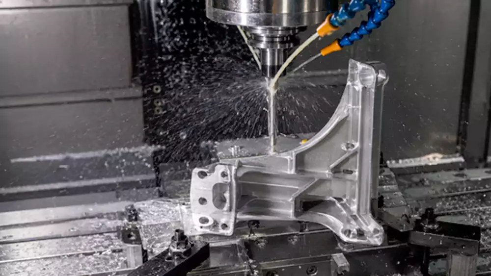
I use CNC milling, drilling, boring, and other operations to finish mounting faces, bolt holes, locating features, and other functional surfaces. I establish the machining datum carefully because a poor datum strategy can transfer casting variation into the final dimensions.
I also avoid machining away more material than necessary. The remaining casting structure still has to carry the engine load.
Case Study: Custom Aluminum Engine Mount Bracket
I once worked on a custom engine mount bracket where the customer needed a lightweight component with several mounting bosses and reinforced ribs. The first design looked acceptable on a static drawing, but I was concerned about vibration around the rib-to-boss transitions.
I used the following production targets for the revised design:
| Parameter | Production target |
|---|---|
| Material | Aluminum alloy |
| Approx. finished weight | 1.15 kg |
| Main wall thickness | 5–7 mm |
| Rib thickness | 4–6 mm |
| Main mounting bore | Ø14 mm |
| Mounting-hole positional tolerance | ±0.05 mm |
| Machined mounting-face flatness | ≤0.05 mm |
| Surface roughness on mounting face | Ra 3.2 μm |
| Heat-treatment condition | T6 |
| Final inspection | Dimensional + visual + NDT as required |
The most important change was not simply tightening the machining tolerance. I changed the structural transition around the mounting boss and improved the casting layout. I then reviewed the load path and vibration behavior before approving the tooling.
After casting, I checked the critical areas for surface defects and dimensional variation. The bracket then went through heat treatment and CNC machining. I used the machined mounting face as an inspection datum and checked the hole positions relative to that datum.
This case reinforced one point that I have learned from more than 20 years around casting operations: I cannot machine my way out of a bad casting design. I need to control the casting first and use machining to finish the functional features.
How Do You Ensure Quality and Select the Right Engine Mount Bracket Supplier?
Supplier selection should focus on process control, not just quoted price. I want to see how a supplier controls casting defects, machining variation, material traceability, and final inspection.
I select an engine mount bracket supplier by checking casting capability, engineering review, CNC machining accuracy, material traceability, inspection equipment, process controls, and the supplier's ability to validate vibration and thermal fatigue before mass production.
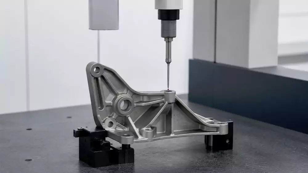
When I evaluate a supplier, I start with the engineering process. A supplier that only waits for the customer to provide a finished drawing may miss manufacturing risks that could have been solved earlier.
I prefer a supplier that reviews the design before tooling. I want to know whether the supplier can identify thin sections, difficult filling areas, shrinkage risks, machining datum problems, and stress concentrations.
I also check the quality system at each stage.
| Quality stage | What I expect |
|---|---|
| Incoming material | Material identification and certification |
| Casting | Controlled process parameters and defect inspection |
| Heat treatment | Controlled cycle and documented results |
| CNC machining | Stable fixtures, datums, and tool control |
| Dimensional inspection | CMM or appropriate calibrated equipment |
| NDT | Suitable method when internal or surface defects require verification |
| Final inspection | Complete dimensional and visual records |
| Traceability | Clear connection between parts, materials, and inspection data |
For engine mount brackets, I pay special attention to internal casting quality. A bracket can look clean on the outside while containing internal shrinkage or porosity. The inspection method should match the risk of the component.
I also ask suppliers for sample inspection reports before approving mass production. I want to compare actual measurements with drawing requirements. If the supplier can explain why a dimension moves during production and how the process keeps it under control, that tells me much more than a simple quality certificate.
Lead time matters as well. A supplier that produces tooling quickly but needs repeated corrections can become slower and more expensive than a supplier that spends more time on the initial engineering review.
For me, the best supplier is not necessarily the one with the lowest quotation. It is the supplier that can control the entire chain from material selection and casting to machining and final inspection. That control reduces the chance that a hidden manufacturing problem reaches the customer's assembly line.
Conclusion
I build engine mount brackets around the real conditions they face in service, not just the dimensions shown on a drawing. Material selection, casting integrity, vibration resistance, thermal fatigue, precision machining, and final inspection all have to work together. When these controls are built into the process from the beginning, I can deliver brackets that are both dimensionally accurate and reliable in demanding engine and powertrain applications. If you are developing a custom engine mount bracket, contact me to review your design, material, casting process, and machining requirements.
-
"Weight transfer", https://en.wikipedia.org/wiki/Weight_transfer. A vehicle engine-mount bracket primarily functions as a load-transfer component, conducting engine forces through a defined load path into the surrounding vehicle body structure while distributing stresses and controlling stiffness and vibration transmission; engineering references on vehicle NVH and structural mechanics describe this load-path-based approach to mounting design. Evidence role: general_support; source type: encyclopedia. Supports: How engine forces move from the mount into the vehicle structure. Scope note: This footnote supports the general concept of load-path-based load transfer for engine mounts, but it does not quantify a specific design guideline or provide criteria unique to the article’s bracket geometry. ↩
-
"The damping characteristics of certain steels, cast irons and other metals", https://www.sciencedirect.com/science/article/abs/pii/0022460X72905603. This supports the comparative engineering rationale that cast iron is valued for stiffness (via elastic modulus and design possibilities) and damping behavior relative to some alternatives, while “better choice” depends on application-specific constraints such as geometry, allowable mass, and fatigue/safety requirements. Evidence role: mechanism; source type: paper. Supports: Cast iron can be a better choice when stiffness, damping, and heavy-duty structural performance are more important than weight.. Scope note: Comparative “better” performance is not universal; it depends on grades, heat treatment, microstructure, damping metrics, and system-level design. ↩
-
"Tensile Strength vs. Yield Strength Understanding the Fundamentals", https://www.basilius.com/blog/tensile-strength-vs-yield-strength-understanding-the-fundamentals/. Engineering handbooks and textbooks describe tensile strength and yield strength as measures of a material’s resistance to deformation and permanent (plastic) deformation under applied stress, respectively, which is relevant for component sizing and resistance to permanent deformation in service. Evidence role: definition; source type: encyclopedia. Supports: Tensile and yield strength determines resistance to permanent deformation. Scope note: General definition-level support; does not quantify specific automotive materials or alloys. ↩