
A bearing carrier may look simple, but small errors in its bore, mounting face, or material quality can cause misalignment, vibration, and premature bearing failure.
A bearing carrier supports and locates a bearing within a mechanical assembly. Custom manufacturing combines suitable materials, precision casting, CNC machining, and dimensional inspection to achieve the required fit, alignment, and service life.
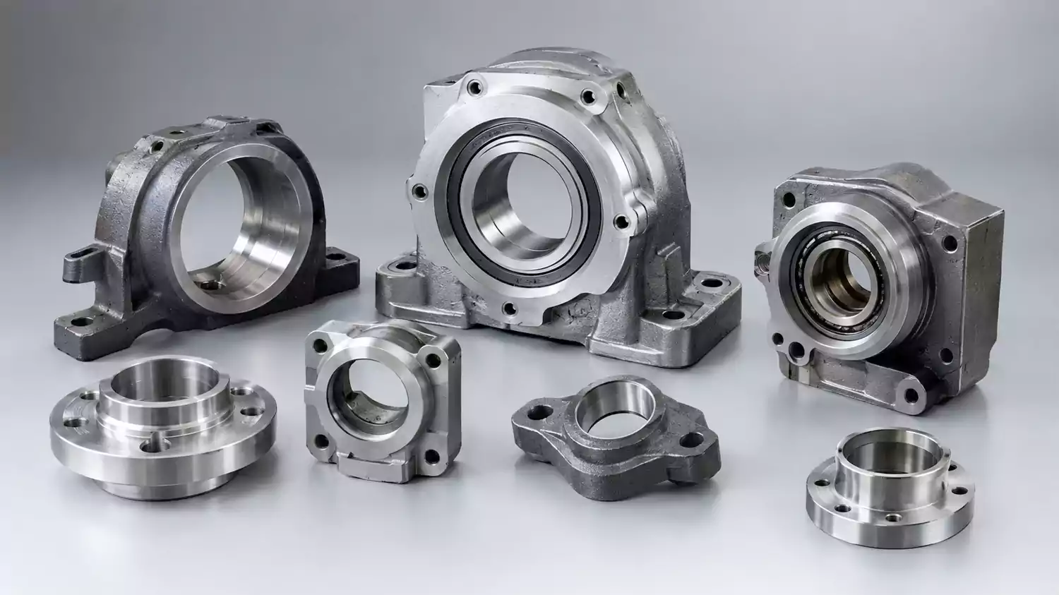
Reliable manufacturing starts long before the first machining operation. The casting must provide a sound structure and enough material for finishing. CNC machining then establishes the critical dimensions and reference datums. Understanding how these stages work together helps procurement managers and engineers reduce production risks and achieve consistent assembly quality.
What Is a Bearing Carrier and Where Is It Used?
Poor bearing support can lead to shaft misalignment, excess vibration, and uneven loads. These problems may affect the performance of an entire mechanical assembly, even when the bearing itself meets its specifications.
A bearing carrier is a mechanical component that holds and locates a bearing inside a machine or assembly. It typically includes a bearing seat, mounting features, and reference surfaces that control the bearing's position relative to a shaft or other components.
How Does a Bearing Carrier Work?
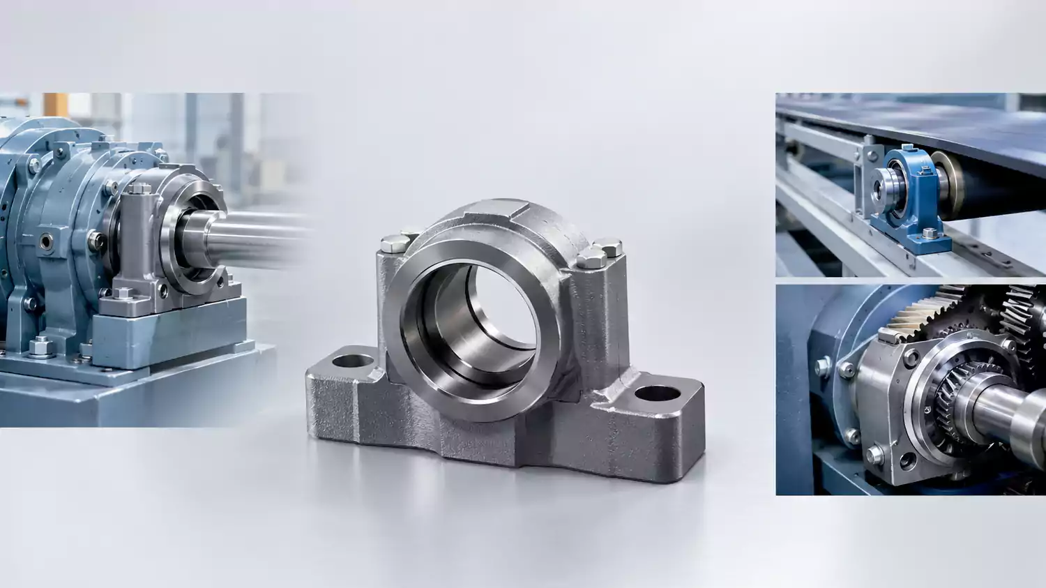
The carrier connects the bearing to the surrounding machine structure. While the bearing allows a shaft or rotating component to move as intended, the carrier keeps it in the correct position and transfers loads to the housing or frame.
Its exact function depends on the application. Some designs support radial loads, while others must also handle axial loads or maintain precise alignment between multiple bearings. The design must account for the bearing type, shaft arrangement, operating speed, temperature, lubrication method, and installation conditions.
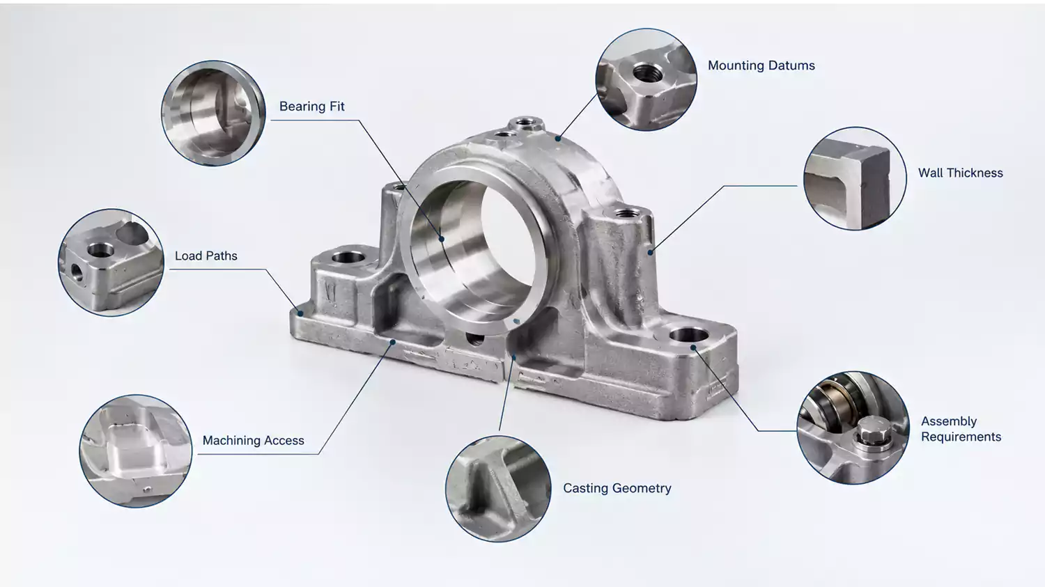
The bearing seat is often the most critical machined feature. Its diameter, roundness, surface finish, and relationship to the mounting datums affect bearing fit and alignment. Mounting faces and bolt holes also matter because they determine how the component sits within the assembly.
Where Are Bearing Carriers Used?
These components are common in mechanical systems that contain rotating shafts or require accurate bearing positioning. Typical applications include:
- Automotive transmissions and drivetrains: Carriers support rotating shafts and maintain alignment within compact assemblies. Their geometry must match the surrounding transmission components and assembly requirements. Related applications include custom transmission parts manufacturing solutions.
- Industrial gearboxes: Bearing supports help locate gears and transfer loads through the gearbox structure.
- Pumps and compressors: Accurate bearing positioning helps maintain shaft alignment during continuous operation.1
- Electric motors and power transmission equipment: Carriers support rotating components and help maintain their intended position.
- Agricultural and industrial machinery: Custom designs accommodate application-specific loads, mounting arrangements, and operating conditions.
A bearing carrier is not always the same as a bearing housing. A housing may enclose and protect the bearing, while a carrier may primarily locate or support it within a larger assembly. Some components perform both functions. Confirming the part's role early helps determine the right material, manufacturing process, and inspection requirements.
What Should You Consider When Designing a Custom Bearing Carrier?
A design that looks correct in CAD may still be difficult to cast, machine, or assemble. Poor feature placement can increase machining costs, while unsuitable wall thickness can lead to casting defects or distortion.
When designing a custom bearing carrier, consider bearing fit, load paths, mounting datums, wall thickness, machining access, casting geometry, and assembly requirements. These factors help ensure that the finished part meets its functional tolerances and remains stable in service.
Start With the Bearing and Assembly Requirements
Begin by identifying the bearing type, its dimensions, the shaft arrangement, and the loads the component must support. Operating speed, temperature range, lubrication conditions, and expected service life also influence the design.2
These requirements affect both geometry and material selection. For example, a carrier used in a high-speed gearbox may need tighter control of bearing alignment than one used in a low-speed, lightly loaded mechanism. Applications involving temperature changes may also require consideration of thermal expansion.
Particular attention should go to the bearing seat and its relationship to the mounting surfaces. A bore can meet its diameter tolerance and still cause assembly problems if it is not perpendicular to a mounting face or aligned with another bore. The engineering drawing should identify functional datums and specify geometric tolerances wherever they affect assembly performance.
Design for Casting and CNC Machining
Investment casting can produce complex near-net shapes, including curved profiles, ribs, and mounting bosses. These features may require extensive material removal if the part is manufactured from a solid billet. However, the design must account for casting limitations as well as final machining requirements.
Abrupt changes in wall thickness can increase the risk of shrinkage defects and uneven cooling. Thin sections may not fill consistently, while poorly designed transitions can create local stress concentrations. Smooth transitions and reasonably uniform wall thickness are generally preferred where the functional design allows them.
Machining access is equally important. The bearing bore, mounting faces, and bolt holes must be accessible to the selected cutting tools and fixtures. Workholding must also be stable enough to prevent thin walls from deforming during machining.
Before production, the design review should cover:
- Bearing-seat dimensions and required fit.
- Datum locations and geometric tolerances.
- Minimum wall thickness and casting transitions.
- Machining allowance on critical surfaces.
- Tool access and workholding stability.
- Assembly clearance, fastener access, and inspection requirements.
Reviewing these details before tooling begins can prevent costly design changes later. It also helps balance component performance with manufacturing cost. Where possible, casting and machining engineers should assess the design together before finalizing the production route.
Which Materials Are Suitable for Custom Bearing Carriers?
Material selection becomes more challenging when the component must withstand heavy loads, temperature changes, vibration, or a demanding operating environment. A material that is easy to cast and machine may not provide the stiffness or durability the application requires.
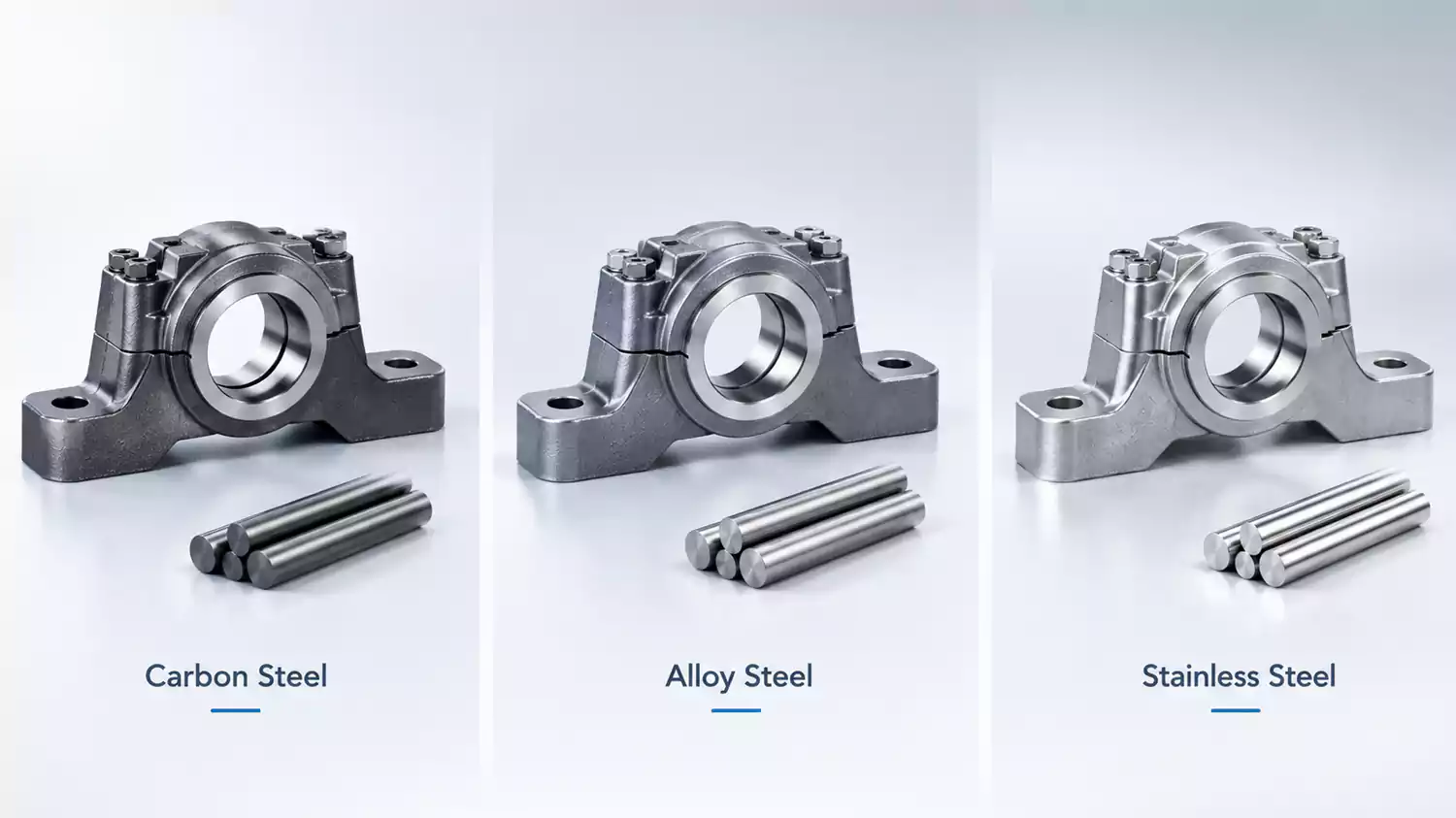
Suitable bearing carrier materials include carbon steel, alloy steel, and selected stainless steels. The best choice depends on load capacity, stiffness, corrosion resistance, operating temperature, casting geometry, machinability, and the required mechanical properties.
Carbon Steel and Alloy Steel
Carbon steel offers a practical balance of strength, machinability, and cost for many industrial applications. The exact grade must match the required mechanical properties and the selected casting process. A grade suitable for a machined bar does not automatically provide identical performance when produced as a casting.
Alloy steel may be a better choice when higher strength or specific toughness is required. Heat treatment can improve certain mechanical properties, but it can also cause dimensional changes that affect machining allowances and inspection plans.3
For either material, the specification should define the required grade, mechanical property limits, heat treatment condition, and material verification method before production begins.
Stainless Steel for Corrosive Environments
Stainless steel is worth considering when corrosion resistance is important. Selected grades may suit equipment exposed to moisture, cleaning fluids, or certain industrial chemicals.
However, stainless steel covers a wide range of grades with different mechanical properties and corrosion resistance. Chloride exposure, temperature, chemical concentration, and surface condition can all affect performance.
Corrosion resistance alone should not determine the choice. Strength, stiffness, casting behavior, machinability, and cost must also match the application.
How Should You Compare Materials Before Production?
The drawing and operating conditions provide the starting point for narrowing the options. The following table offers a general comparison, but the final choice should be based on grade-specific engineering requirements.
| Material family | Main advantages | Important considerations |
|---|---|---|
| Carbon steel castings | Practical strength and broad industrial use | Grade-specific strength, toughness, and corrosion protection |
| Alloy steel castings | Potential for higher strength and tailored heat-treated properties | Heat treatment, distortion, machining difficulty, and cost |
| Stainless steel castings | Corrosion resistance with grade-dependent mechanical properties | Grade selection, machining behavior, and material cost |
The bearing seat also requires careful consideration. The material must remain stable under the actual bearing loads and operating temperatures. Where the design uses a press fit, the engineering team should evaluate material behavior and dimensional changes during assembly and service.
Material specifications should be verified through appropriate documentation and inspection. Depending on the application, this may include material certificates, chemical composition verification, mechanical testing, and heat treatment records.
How Are Bearing Carriers Manufactured?
Casting defects can remain hidden beneath a machined surface, even when the finished component passes dimensional inspection. CNC machining cannot repair every internal defect or compensate for an unstable casting process.
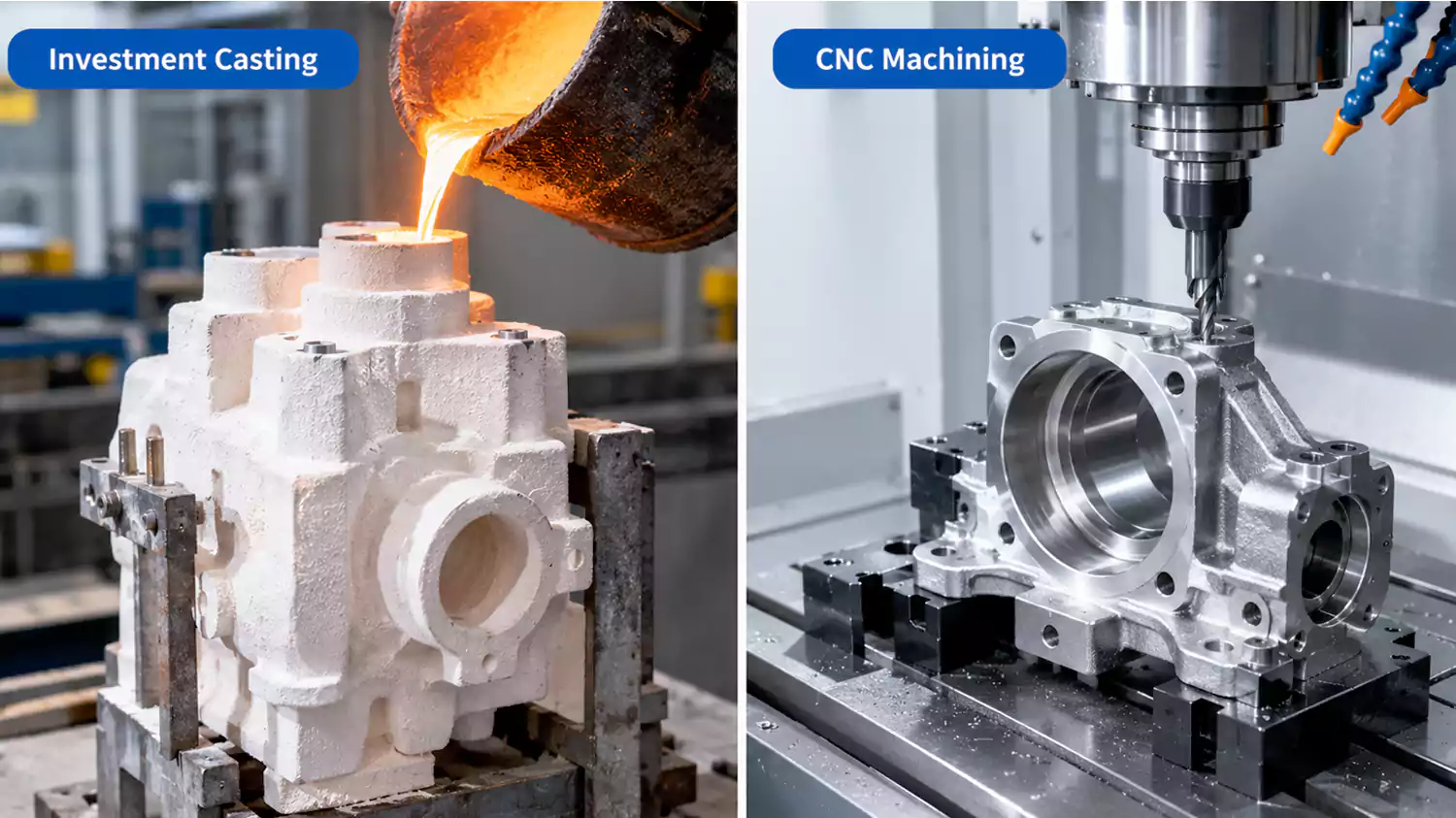
Custom bearing carriers can be manufactured by investment casting followed by CNC machining. Casting produces the near-net shape, while CNC machining establishes the critical bearing bore, mounting faces, holes, and reference datums. Heat treatment and inspection are added when the material and application require them.
Step 1: Investment Casting Establishes the Foundation
The process begins with how molten metal fills the mold and solidifies. Investment casting generally includes wax pattern production, ceramic shell preparation, wax removal, metal pouring, solidification, shell removal, and finishing of the raw casting.
The quality of the casting affects every later operation. Poor feeding design, unsuitable pouring conditions, or uneven solidification can contribute to shrinkage defects, porosity, and dimensional variation. These problems are particularly important around the bearing seat and mounting bosses, where machining may expose hidden defects.
The casting design must provide enough stock for the planned machining operations. Excessive allowance increases cycle time, tool wear, and material waste. Insufficient allowance can leave a critical surface incomplete if the raw casting varies more than expected.
A reliable casting process accounts for geometry, the feeding system, material properties, and required final dimensions. The goal is to produce a repeatable near-net shape that provides a sound starting point for machining.
Step 2: Heat Treatment and Casting Preparation
Some bearing carriers require heat treatment to achieve specified mechanical properties. The appropriate process depends on the alloy and engineering requirements.
Temperature, holding time, cooling conditions, and the condition of the incoming material can all affect the final properties. Heat treatment may also change dimensions. For this reason, critical surfaces should not be finish-machined before dimensionally significant thermal operations are complete unless the process plan specifically accounts for those changes.
After casting and any required heat treatment, the part may need cleaning, gate and riser removal, and preliminary inspection. Depending on the application, visual inspection or nondestructive testing can identify defects before the component moves to more expensive machining operations.
Step 3: CNC Machining Controls the Critical Features
Once the casting passes the required checks, CNC machining establishes the final functional geometry. The machining plan should use the primary mounting datum as a reference and control its relationship to the bearing bore and other critical features.
The sequence may include rough milling, drilling, boring, semi-finishing, and final finishing. The actual route depends on the design, material, machine configuration, and required tolerances.
Uneven stock removal and poor workholding can release residual stress or cause local deformation, especially in thin sections. For demanding components, rough machining followed by a suitable stabilization step and finish machining may improve dimensional consistency. The need for such a step should be determined by the material and process requirements.
Step 4: A Custom Bearing Carrier Manufacturing Example
Consider a hypothetical custom carrier for an industrial gearbox. The following values are illustrative engineering targets, not measured results from a completed customer order.
| Parameter | Illustrative project requirement |
|---|---|
| Component | Custom gearbox bearing carrier |
| Raw manufacturing process | Investment casting |
| Material | Specified carbon steel casting grade |
| Approximate overall size | 160 × 120 × 65 mm |
| Critical bearing bore | Ø60 mm |
| Bore dimensional tolerance | ±0.015 mm |
| Bore-to-mounting-datum perpendicularity | 0.03 mm |
| Mounting-face flatness | 0.03 mm |
| Surface finish at bearing seat | Ra 1.6 µm |
| Production quantity | 500 pieces per batch |
| Primary inspection method | CMM and calibrated bore measurement equipment |
The first step is to review the drawing and confirm the bearing fit, datum scheme, and inspection method with the customer. The proposed casting geometry must provide adequate machining allowance around the Ø60 mm bore and mounting face.
During initial production, representative raw castings should be inspected before the full batch enters CNC machining. Visible defects must be checked, and additional testing should be applied when required by the component specification or risk assessment.
For machining, a repeatable fixture should be established around the agreed datums. The mounting face provides a stable reference, while the bearing bore is machined in a controlled sequence to achieve the specified diameter and geometric relationship. Final inspection verifies the bore diameter, perpendicularity, flatness, and surface finish using suitable calibrated equipment.
The main lesson is that dimensional targets alone do not guarantee success. Casting quality, fixture design, machining sequence, and inspection methods must all support the same functional requirements.
What Tolerances and Quality Checks Matter for Bearing Carriers?
Not every dimension on a bearing carrier needs the same tolerance. Applying unnecessarily tight tolerances increases manufacturing costs, while loose control of critical features can cause bearing fit and alignment problems.
Important bearing carrier quality checks include bearing-bore diameter, roundness, cylindricity where specified, positional accuracy, geometric relationships to mounting datums, surface finish, material properties, and casting integrity. Inspection priorities should follow the part's function, engineering drawing, and application-specific acceptance criteria.
Bearing-Bore Accuracy and Geometric Control
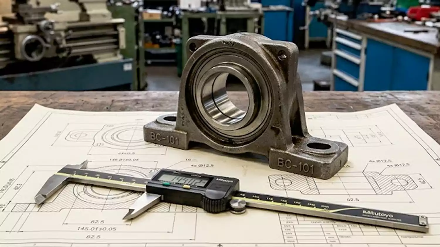
The bearing bore directly affects how the bearing is located and supported. Its required diameter tolerance depends on the bearing type, fit designation, material, load conditions, and operating temperature. No single tolerance is appropriate for every application.
Diameter alone is not enough. A bore may meet its nominal size but still have unacceptable ovality, taper, or alignment. Where specified, inspection should also cover roundness, cylindricity, position, and the bore's relationship to the mounting datums.
The drawing should define these requirements clearly. Tight tolerances should be reserved for features where they serve a functional purpose. Inspection can then focus on the surfaces and relationships that influence assembly, load transfer, and service life.
Casting Quality Before Machining
Raw casting quality should be checked before machining whenever the risk and specification justify it. Surface defects may be visible during visual inspection, but internal porosity and shrinkage may require other methods.
Depending on the component's criticality, the inspection plan may include dimensional checks on the raw casting, liquid penetrant testing, magnetic particle testing for suitable ferromagnetic materials, radiographic testing, or other approved nondestructive examination methods.
Each method has limitations. The appropriate technique depends on the material, defect type, component geometry, acceptance criteria, and applicable specification. These requirements should be agreed upon before production rather than after a defect appears.
CNC Inspection and Process Consistency
Measurement methods should match the features being checked. A coordinate measuring machine (CMM) can evaluate relationships between datums and complex geometric features. Bore gauges or other suitable calibrated instruments can verify internal diameters, while surface roughness equipment measures the specified finish.
First-article inspection and ongoing production control serve different purposes. A first article confirms that the manufacturing route can meet the drawing. During batch production, process monitoring and scheduled inspection help detect tool wear, fixture movement, and dimensional drift before they affect a large number of parts.
A practical quality plan may include:
- Raw casting visual and dimensional inspection.
- Material verification and required mechanical testing.
- Heat treatment records where applicable.
- First-article dimensional inspection.
- Bore diameter and geometric tolerance verification.
- Surface finish checks on functional surfaces.
- Final inspection reports and traceability records.
For repeat orders, previous inspection results and nonconformities can reveal recurring problems and help improve the manufacturing process.
Why Must Casting and Machining Work Together?
Reliable results come from treating casting and machining as one manufacturing system. Casting controls the initial geometry, material soundness, and machining stock. CNC machining establishes the final dimensions and functional relationships.
If the raw casting contains a defect in a critical area, machining may expose it. Poor datum selection can also produce dimensional inconsistency, even when the casting itself is sound. Similarly, an inspection plan that checks only bore diameter may miss a geometric error that affects assembly.
The complete manufacturing plan must connect casting design, process control, machining strategy, and final inspection. The objective is not simply to make one part pass inspection. It is to establish a repeatable process that delivers consistent quality across the full production batch.
Conclusion
Reliable bearing carrier manufacturing starts with sound castings and continues through controlled CNC machining and inspection. By managing material quality, machining allowances, bearing-bore accuracy, and critical datums from the beginning, manufacturers can reduce production risks and improve assembly reliability.
For a custom project, share the part drawing, material requirements, production volume, and critical tolerances with a manufacturing partner to evaluate the most suitable process.
-
"(PDF) Shaft alignment on pumps", https://www.academia.edu/35644424/Shaft_alignment_on_pumps. Research and engineering guidance on rotating machinery links proper bearing positioning and alignment with maintaining the intended shaft-running condition in pumps and compressors. Evidence role: general_support; source type: research. Supports: Accurate bearing positioning contributes to shaft alignment in pumps and compressors.. Scope note: This supports the general relationship, not a guarantee of continuous operation or performance in every machine. ↩
-
"Lubricants, Intervals, Service Life | TEA", https://technische-antriebselemente.de/en/guides/lubrication/. Engineering guidance on bearing selection identifies operating speed, temperature, lubrication, and required service life as relevant operating conditions. Evidence role: general_support; source type: education. Supports: Engineering references identify speed, operating temperature, lubrication, and required life as operating conditions considered in bearing selection and design.. Scope note: General bearing-selection guidance does not establish the appropriate values or design response for a particular carrier. ↩
-
"Effect of heat treatment on the microstructure and ...", https://www.nature.com/articles/s41598-025-17582-1. Studies of steel heat treatment document changes in mechanical properties and dimensional distortion associated with thermal processing and transformation stresses. Evidence role: mechanism; source type: paper. Supports: Heat treatment can improve certain mechanical properties, but it can also cause dimensional changes that affect machining allowances and inspection plans.. Scope note: Reported distortion varies with alloy composition, component geometry, heating and cooling practice, and restraint; the source does not establish a universal machining allowance. ↩