
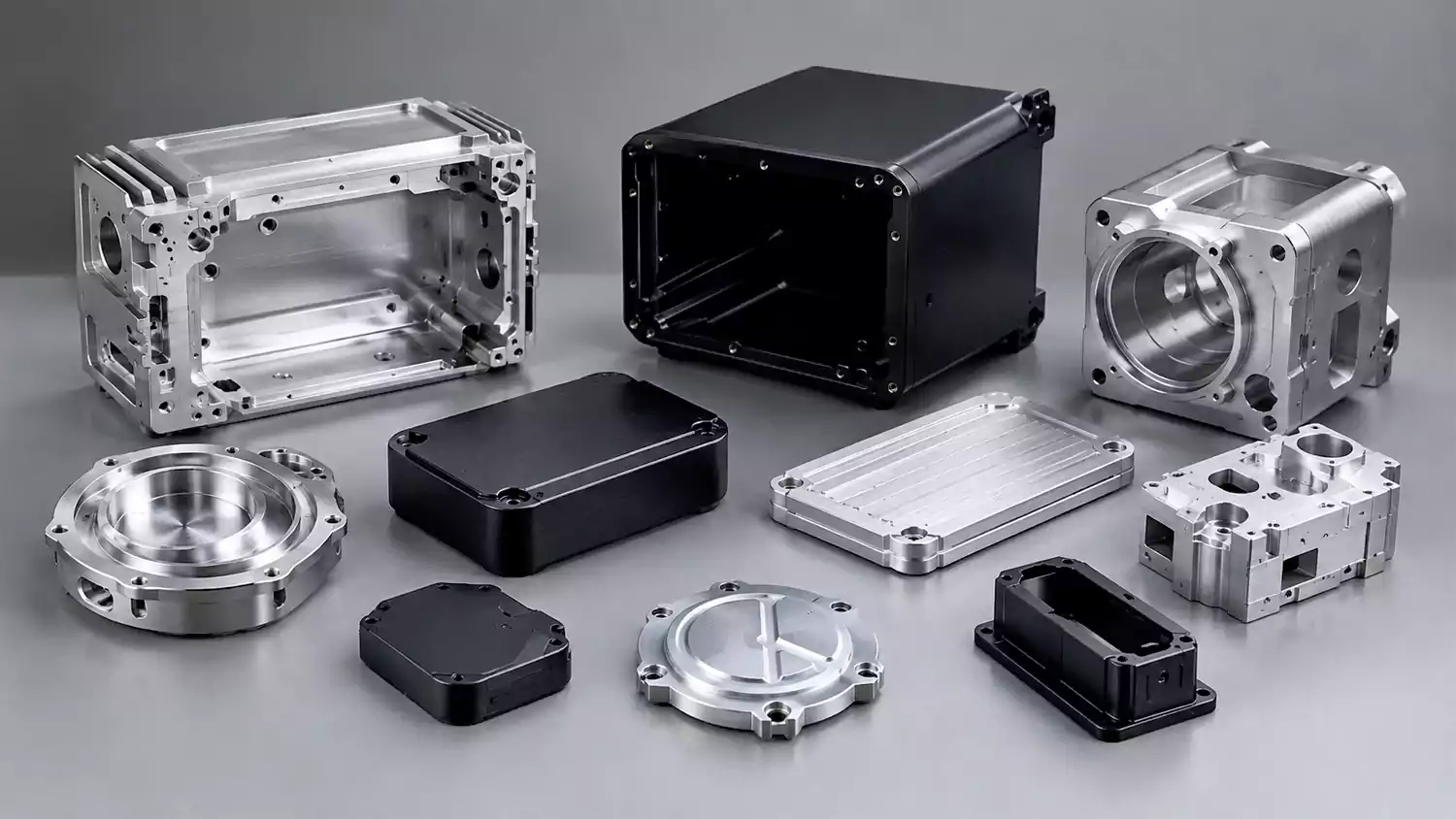
Custom housings, enclosures, and covers can look simple in CAD, but poor design choices can lead to high machining costs, part distortion, and assembly problems.
Cost-effective CNC machined housings start with five key design decisions: machining access, reliable workholding, material selection, surface finish, and manufacturing efficiency. Getting these details right helps reduce machining time, prevent quality issues, and keep parts within budget without compromising their function.
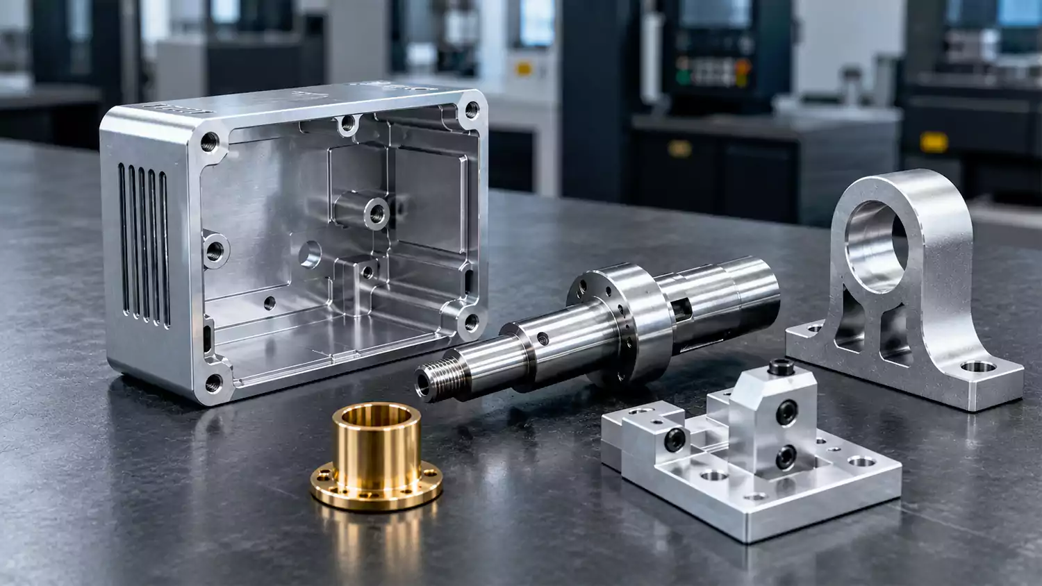
A housing drawing defines what a part should look like, but the manufacturing process determines how efficiently it can be made. Deep pockets, thin walls, tight tolerances, and difficult clamping positions can all increase production costs. A few changes during the design stage can often prevent expensive problems later. With more than 20 years of CNC machining experience, I have learned that three rules matter from the start: the cutting tool must reach the feature, the workpiece must be held securely, and the part must remain stable during machining. These principles provide a practical starting point for engineers and purchasing teams evaluating custom housing designs.
What Are the Key Design Requirements for CNC Machined Housings?
Housings often combine mounting holes, internal cavities, precision bores, and thin walls in a single component. If these features are not designed with machining in mind, even a straightforward part can require extra setups, special tools, and costly rework.
The key design requirements for CNC machined housings are accessible machining features, stable workholding, functional tolerances, sufficient wall thickness, and clearly defined datums. These requirements help control tool interference, vibration, dimensional errors, and deformation during machining and assembly.
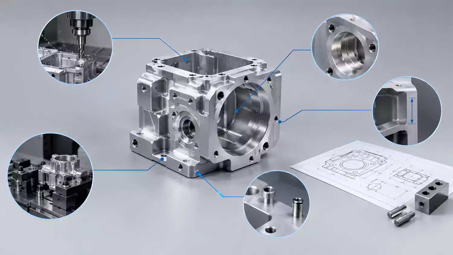
Design for Tool Access and Machining Operations
The first step is to check whether standard milling cutters, drills, and boring tools can reach every required feature. A deep, narrow pocket may need a long tool with limited rigidity. This can increase vibration, reduce surface quality, and extend machining time.
Where the design allows, wider pockets, larger internal corner radii, and fewer unnecessary deep features can simplify production. Internal corners should match practical cutter sizes. If a sharp internal corner is essential, the drawing should identify whether a special tool or a secondary operation is acceptable.
Hole positions, internal passages, and mounting features also affect machining access. Features that require machining from several directions may need additional setups. Each setup adds handling time and creates another opportunity for alignment errors.
Keep Workholding and Tolerances Practical
A CNC machine needs a stable way to hold the workpiece. Irregular housings and thin flanges can be difficult to fixture without distortion. Flat reference surfaces, accessible clamping areas, and clear datum features help the machinist locate the part consistently.
Tolerances should reflect the function of each feature. Bearing bores, sealing faces, and alignment surfaces may need tight tolerances, while cosmetic surfaces and non-functional external walls may allow wider limits.
For example, a housing may require a precise bearing bore but only a general tolerance on its outer profile. Applying tight tolerances to every dimension can increase machining and inspection costs without improving assembly performance.
The practical goal is to make functional features precise, keep the machining process accessible, and avoid tolerances that the assembly does not need.
How Do You Choose Materials and Design Housing Structures?
Material selection affects more than strength. It also influences machining behavior, weight, heat transfer, corrosion resistance, and production cost. A material that works well for one housing may be unsuitable for another.
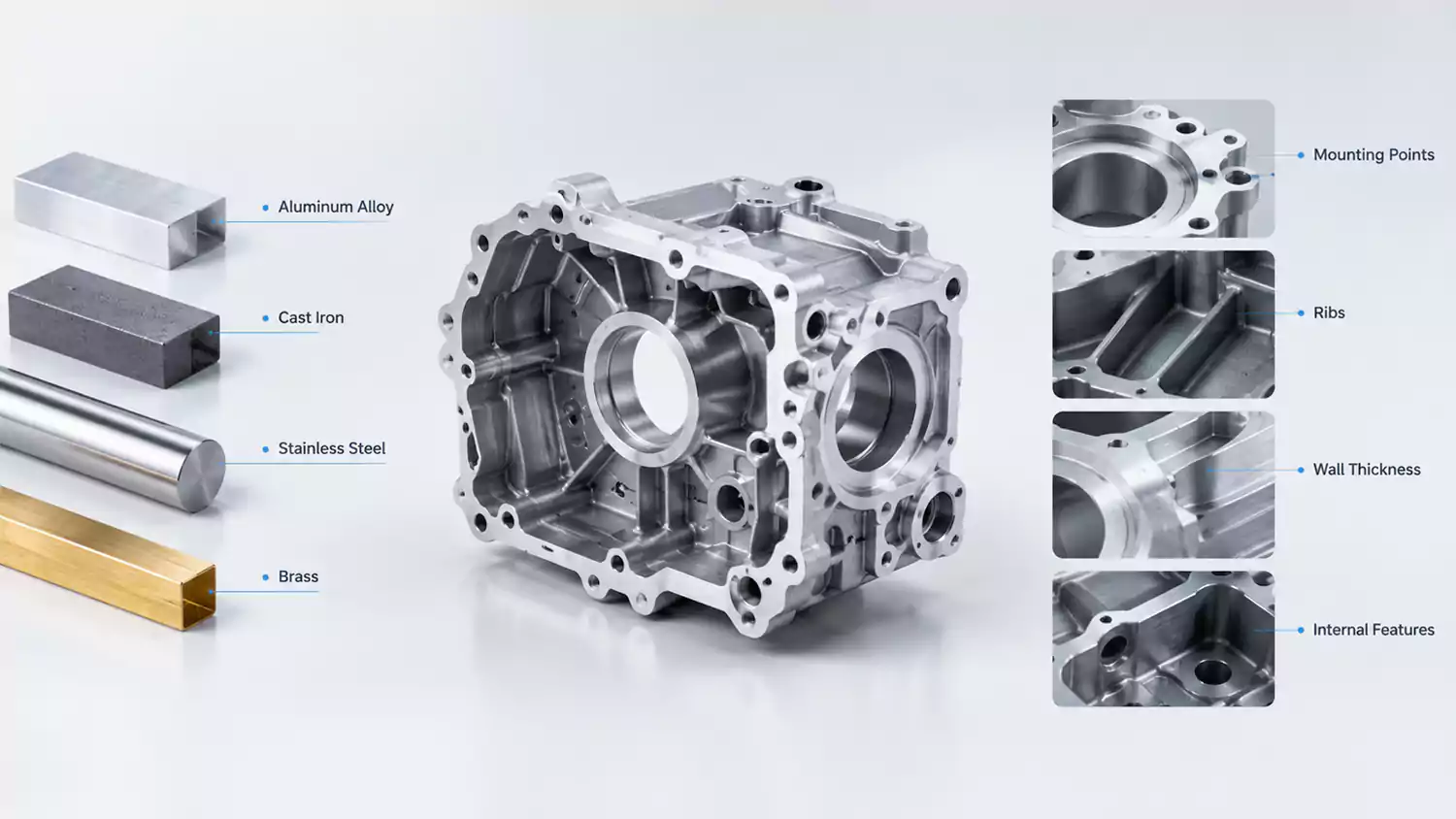
The best material for a CNC machined housing depends on mechanical loads, operating temperature, weight limits, corrosion exposure, thermal requirements, and machinability. Wall thickness, ribs, mounting points, and internal features should then be designed around the material's properties and the housing's functional requirements.
Compare Common Housing Materials
The most suitable material depends on the working environment and the part's required performance. Aluminum alloys, carbon steel, stainless steel, and engineering plastics are common options, but each has different manufacturing considerations.
| Material | Main advantages | Design considerations | Typical applications |
|---|---|---|---|
| Aluminum alloys | Low weight, good machinability, good thermal conductivity | Thin walls may distort; surface protection may be needed | Electronic enclosures, motor housings, lightweight equipment |
| Carbon steel | Good strength, broad availability | Corrosion protection may be required; machinability depends on grade | Industrial machinery housings, mounting structures |
| Stainless steel | Corrosion resistance and durability | Some grades are more difficult to machine and may generate more heat | Food processing equipment, chemical systems, outdoor enclosures |
| Engineering plastics | Low weight, electrical insulation, corrosion resistance | Thermal expansion, creep, and stiffness require attention1 | Electrical enclosures, instrument covers, fluid-handling components |
Material selection should not rely on strength values alone. Aluminum may be a good choice when low weight and heat dissipation matter. Stainless steel may be more suitable for a corrosive environment. The operating conditions, expected service life, and total manufacturing cost should guide the decision.
Design Wall Thickness, Ribs, and Mounting Features
Wall thickness is one of the first structural details to review. Thin walls reduce material use, but they can flex under cutting forces and clamping pressure. Excessively thick walls can add weight and require more material removal.
Ribs and local reinforcement can improve stiffness where the design needs additional support. However, ribs should not block tool access or create unnecessary machining operations. Mounting bosses also need sufficient material around threaded holes and fasteners.
For precision housings, the order of roughing and finishing operations matters. Removing large amounts of material can release internal stress and cause the part to move.2 Depending on the material, stock condition, and geometry, a suitable process may include rough machining, stress relief where required, and finish machining after the geometry has stabilized.
The design must account for the material's behavior rather than assume it will remain perfectly stable throughout production. This is especially important when a housing combines thin walls with tight bore tolerances or flat sealing surfaces.
Which Surface Finishes Are Best for CNC Machined Housings?
Surface finish affects appearance, sealing, wear, corrosion resistance, and assembly. A uniform finish across the entire housing is rarely necessary. The right choice depends on the function and exposure of each surface.
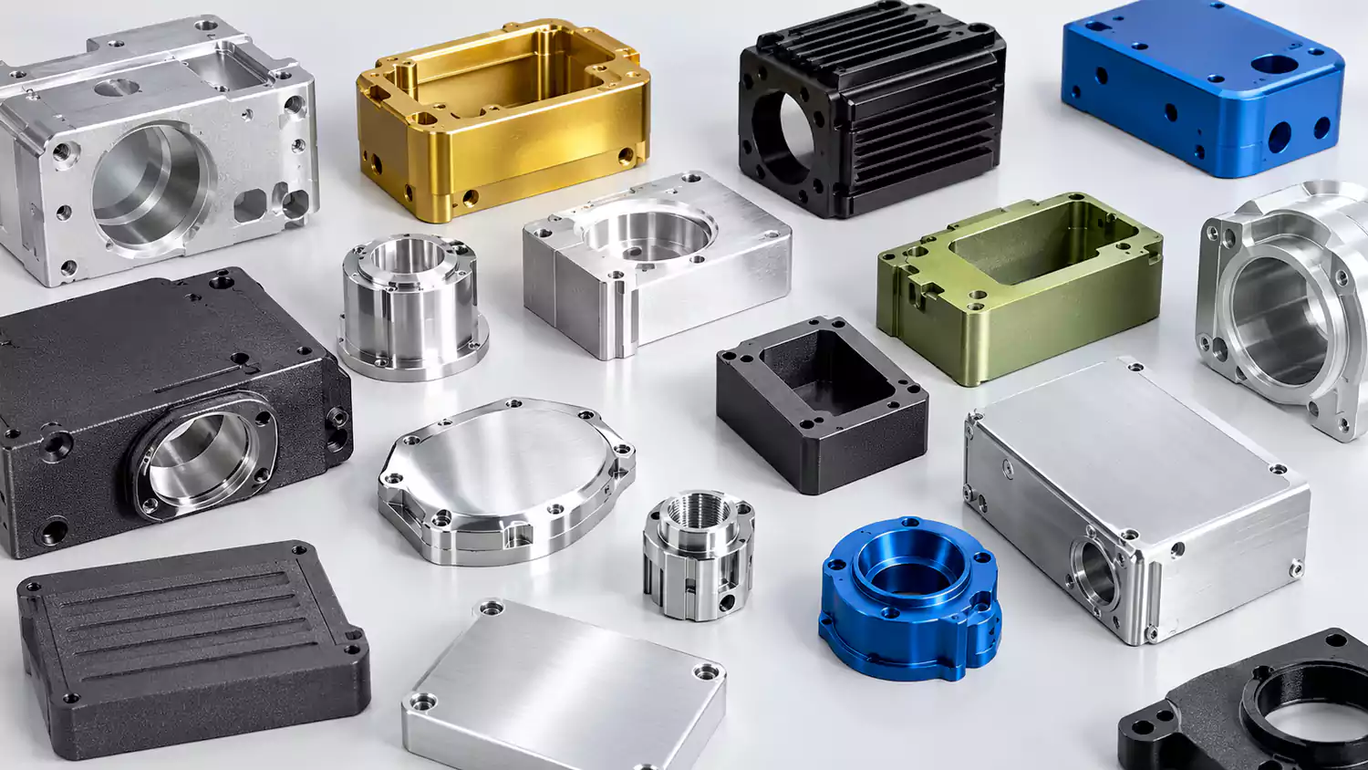
The best surface finish for a CNC machined housing depends on its intended use. Precision bores and sealing faces need controlled dimensions and surface roughness, while external surfaces may use bead blasting, anodizing, painting, or other treatments for appearance and corrosion protection.
Match Surface Finish to Function
Housing surfaces should be classified by function before the finishing process is selected.
- Bearing bores and alignment features: These require controlled dimensions, geometry, and surface quality. Requirements should reflect the bearing, shaft, or mating component.
- Sealing faces: These need suitable flatness and surface roughness for the specified gasket or sealing method. A decorative coating may not be appropriate.
- External surfaces: These may use bead blasting, brushing, painting, or other treatments when appearance and corrosion protection matter.
- Threaded holes and mating interfaces: These need protection from coating buildup that could affect assembly, thread engagement, or dimensional fit.
Anodizing deserves special attention on aluminum housings. It can improve corrosion and wear resistance, but coating thickness may affect hole sizes, fits, and mating dimensions. Drawings should identify critical features and clarify whether dimensions apply before or after finishing.
Specify Surface Roughness and Coatings Clearly
A surface roughness value, such as Ra 1.6 μm or Ra 3.2 μm, describes surface texture. It does not replace dimensional tolerances, flatness requirements, or geometric controls.
Specifying an unnecessarily fine finish on every surface can increase machining time, require additional passes, and add inspection costs. If a surface does not affect sealing, alignment, wear, or appearance, a more practical requirement may be sufficient.
The same principle applies to coatings. Anodizing can suit aluminum housings, while painting or powder coating may suit some external steel or aluminum enclosures. Stainless steel may not need an additional coating in certain environments, although passivation or other treatments may still be appropriate.
Before a drawing is released, the finish specification should identify the required process, relevant standards where applicable, and any dimensions that must remain within tolerance after treatment. Clear requirements help prevent disagreements between the designer, machining supplier, and finishing supplier.
How Can You Optimize Housing Design for CNC Machining Cost and Efficiency?
The cost of a custom housing depends on more than raw material. Machining time, fixture design, setup count, tool selection, inspection, finishing, and production quantity all influence the final quotation.
CNC housing costs can be reduced by simplifying difficult features, limiting unnecessary setups, choosing practical tolerances, improving tool access, and matching the manufacturing process to the order quantity. These changes can lower machining time and production complexity without compromising functional requirements.
Reduce Setups and Unnecessary Machining
The number of times a housing must be repositioned during production is an important cost factor. A design that allows several features to be machined in one setup can reduce handling, alignment work, and cycle time.
Standardizing hole sizes, thread types, internal radii, and tool requirements can also simplify production. Drawings with many unique features may require extra tools and more programming. Where function allows, standard sizes can reduce setup complexity and improve repeatability.
Material removal is another major consideration. A solid block machined into a complex enclosure may generate a large amount of scrap. For some designs, a near-net-shape blank, casting, or alternative manufacturing route may offer better economics, especially at higher production volumes.
For transmission-related components, the choice between machining from solid stock and using a cast blank can be especially important. Parts such as gearbox housings, transmission covers, and bearing carriers may benefit from a combined casting and CNC machining approach when their geometry and production volume support it. The most suitable route depends on the design, material requirements, and critical machined features, as explained in these transmission parts manufacturing solutions.
Practical Case Study: Reviewing a Custom Aluminum Housing
Consider a hypothetical aluminum equipment housing that needs a central cavity, mounting holes, a precision bore, and a finished external surface. The following values illustrate how a design review might improve manufacturability. They are illustrative estimates, not actual Allied Metal production records or a guaranteed cost quotation.
| Parameter | Initial design | Revised design |
|---|---|---|
| Material | Aluminum 6061-T6 | Aluminum 6061-T6 |
| Overall size | 160 × 120 × 50 mm | 160 × 120 × 50 mm |
| Minimum wall thickness | 2.0 mm | 3.0 mm in selected flexible areas |
| Internal corner radius | 1.0 mm | 3.0 mm where function allows |
| Machining setups | 4 | 3 |
| Estimated machining time per part | 75 minutes | 55 minutes |
| Critical bore tolerance | ±0.02 mm | ±0.02 mm |
| External finish | Bead blast and anodize | Bead blast and anodize |
In this example, the revised design uses larger internal radii and adds material to selected flexible walls. It also reduces the number of setups from four to three. These changes aim to improve tool rigidity and workholding while preserving the critical bore tolerance.
The estimated machining time falls from 75 minutes to 55 minutes, a reduction of approximately 27%. At a hypothetical machine rate of $60 per hour, the estimated machine-time cost falls from $75 to $55 per part. This comparison excludes material, programming, tooling, inspection, finishing, and setup costs, so it does not represent the total part price.
The proposed changes would still need engineering approval before production. The revised wall thickness must meet weight and packaging requirements, and the larger radius must not interfere with internal components.3 A design revision only creates value when it reduces manufacturing effort without introducing new functional problems.
What Should You Consider When Sourcing Custom CNC Machined Housings?
A good housing drawing is only one part of a successful sourcing project. The supplier must understand the functional requirements, plan a suitable manufacturing process, control critical dimensions, and deliver consistent quality throughout the order.
When sourcing custom CNC machined housings, evaluate the supplier's machining capabilities, material control, inspection methods, production capacity, finishing options, lead time, and communication. A reliable supplier should also identify design risks and provide a clear quotation based on the actual drawing requirements.
What Should You Include in an RFQ?
A complete drawing package helps suppliers quote accurately and identify manufacturing risks before production begins. Missing information can lead to assumptions, quotation delays, and differences between the expected part and the delivered component.
A useful RFQ package should include:
- 2D engineering drawings: Include dimensions, tolerances, datums, threads, geometric tolerances, and surface finish requirements.
- 3D CAD files: STEP files are commonly used to communicate overall geometry. The 2D drawing should define the controlling requirements.
- Material specifications: Identify the exact alloy or grade, temper or condition where relevant, and any material certification requirements.
- Surface treatment requirements: State the process, appearance expectations, and critical dimensions affected by coating.
- Order quantities: Provide prototype quantity, initial production quantity, and expected annual demand when available.
- Inspection requirements: Identify critical dimensions, required reports, material certificates, and any special acceptance criteria.
- Delivery and packaging details: State the required delivery date, shipping destination, and protection needed for finished surfaces.
Critical assembly features should also be identified in the RFQ. This helps the supplier focus inspection resources on dimensions that affect fit, alignment, sealing, and overall product performance.
How Do You Compare Suppliers Beyond Unit Price?
The proposed manufacturing process matters as much as the quoted price. A low quotation may exclude inspection, finishing, special tooling, or other requirements that later appear as additional charges.
Ask how the supplier plans to machine the housing, control distortion, inspect critical bores, and protect finished surfaces. For complex parts, a review of the proposed process can reveal whether the supplier understands the actual manufacturing risks.
The supplier should also be able to support the project's production needs. A prototype may require flexible workholding and additional engineering time. Larger batches may benefit from dedicated fixtures, standardized operations, and more efficient inspection methods.
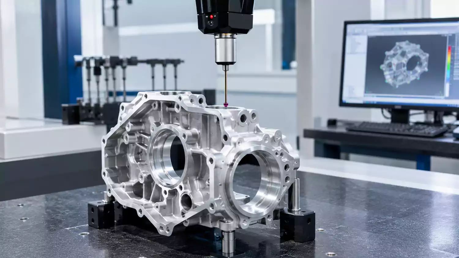
Quality control should be built into the manufacturing process rather than left until final inspection. Material verification, in-process measurements, and final inspection each help detect different types of problems.
At Allied Metal, our approach to custom CNC machining combines practical design-for-manufacturing reviews with attention to dimensional accuracy, material behavior, and production efficiency. The goal is to identify risks early and develop a process that balances quality, lead time, and cost. Clear drawings and direct communication help both the buyer and supplier make better decisions before production starts.
Conclusion
A well-designed CNC machined housing balances functional precision with practical manufacturing requirements. By ensuring tool access, stable workholding, suitable materials, and realistic tolerances, you can reduce avoidable costs and production risks. Share your drawings with Allied Metal for a manufacturing review and a quotation tailored to your project.

-
"Creep (deformation)", https://en.wikipedia.org/wiki/Creep_(deformation). Polymer materials science sources describe thermoplastics as viscoelastic: stiffness depends on temperature and time, creep can accumulate under sustained load, and thermal expansion is generally larger than for metals. Evidence role: general_support; source type: encyclopedia. Supports: Engineering plastics require attention to thermal expansion, creep, and stiffness in design.. Scope note: Values vary widely by polymer family and reinforcement; the source supports qualitative design concerns rather than specific allowable values. ↩
-
"Simulating the effects of machining induced residual stress ...", https://www.sciencedirect.com/science/article/pii/S2212827126007559. Reviews of machining distortion describe how removing material changes the balance of residual stresses in a workpiece, allowing deformation as stresses redistribute; roughing, stress relief, and finishing are used to manage this effect. Evidence role: mechanism; source type: paper. Supports: Removing large amounts of material can redistribute residual stress and cause the part to move.. Scope note: The magnitude and direction of distortion are material- and process-specific, so the source supports the general mechanism rather than a universal machining sequence. ↩
-
"Thin Wall Milling at a Maximized Axial Depth of Cut - PMC - NIH", https://pmc.ncbi.nlm.nih.gov/articles/PMC12654576/. Studies of thin-wall machining document deflection and distortion under cutting and clamping loads, supporting attention to wall stiffness and workholding. Evidence role: mechanism; source type: paper. Supports: Wall thickness affects stiffness and workholding behavior in machining, while the design must also satisfy functional weight and packaging limits.. Scope note: The evidence explains a general risk and does not establish that the illustrative change from 2.0 mm to 3.0 mm is necessary or suitable for this hypothetical housing. ↩