Last updated on April 24, 2026, by Lucy
Parts often fail without warning, and the root cause is often misunderstood. I have seen many components break early because shear stress was ignored in design and process planning.
Shear stress is the force acting parallel to a surface divided by the area, and it matters because it directly causes sliding failure, fatigue cracks, and early breakdown in components under side loads.
I learned early that many failures are not caused by how much force is applied, but how it is applied. Shear stress is one of the most overlooked factors in real-world manufacturing.
Understanding Shear Stress in Engineering?
Many engineers focus on tensile strength first. That is common. But I often see designs fail because shear stress was not properly considered.
Shear stress is calculated as force divided by area acting parallel to a surface, and it is critical in parts where loads cause internal sliding rather than pulling, such as bolts, shafts, and contact interfaces.
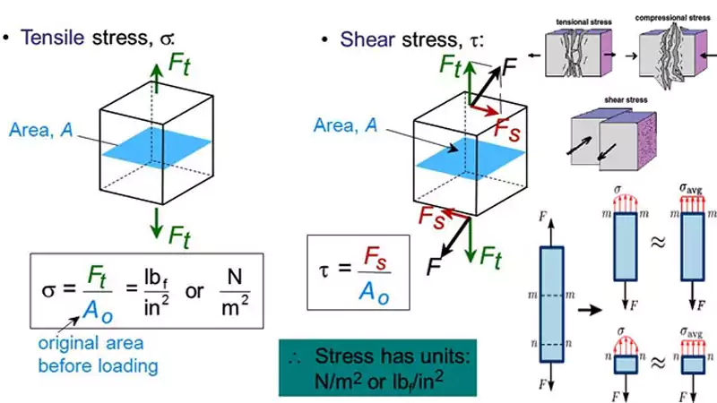
In engineering practice, shear stress is usually expressed in a standard form like the one below. I use it as a quick reference rather than focusing on the math itself:
τ = F / A
This format keeps things clear and practical. In real projects, I care more about how the material behaves than the equation itself. The structure inside the metal often matters more than the formula on paper.
What Is Shear Stress? (Simple Explanation)
I often explain it using a simple idea. Imagine pushing a stack of cards sideways. Each layer slides. That sliding force per area is shear stress. This is exactly what happens inside metal under load.
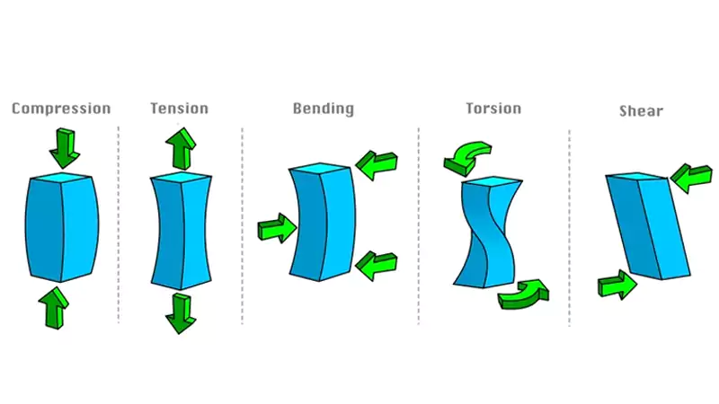
How Shear Stress Differs from Tensile Stress
I like to break it down clearly:
| Factor | Shear Stress | Tensile Stress |
|---|---|---|
| Load direction | Parallel to surface | Perpendicular |
| Failure mode | Sliding fracture | Pull-apart fracture |
| Common parts | Bolts, pins, shafts1 | Rods, cables |
This difference is critical. A part designed for tension may fail quickly under shear.
Common Units and Measurement in Industry
In most of my projects, we use MPa. In US markets, psi is also common. Engineers rely on material data and simulations, but I always remind teams that numbers alone are not enough. Real performance depends on microstructure2.
Where Shear Stress Occurs and Why It Causes Failure?
Many components look perfect during inspection, yet fail in operation. I have seen this happen many times, especially in dynamic systems.
Shear stress occurs in rotating, fastening, and load transfer components, and it causes failure through crack initiation, fatigue growth, and sudden fracture when internal material layers cannot resist sliding forces.
This is where engineering theory meets real-world failure. The challenge is not identifying shear stress, but understanding how it evolves during service.
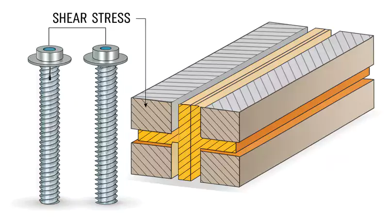
Typical Components Under Shear Stress
In my experience, shear stress is common in:
- Shafts under torque
- Bolts and fasteners under lateral load
- Gear contact surfaces
- Hydraulic valve systems
These parts often operate under repeated stress cycles. That increases the risk of failure.
How Shear Stress Leads to Failure
Shear Fracture
This is a direct failure mode. The material fails along a plane due to excessive sliding force. I have seen this happen in parts with weak internal structure.
Fatigue Under Cyclic Shear
This is more subtle. Small cracks form and grow slowly. The part may appear fine until sudden failure occurs.
Crack Initiation in Cast vs Machined Parts
This is a key difference. Cast parts may contain internal defects if not well controlled. Machined parts often have residual stress. Both conditions can trigger cracks under shear.
Case Study: Gear Shaft Failure in Industrial Pump
I once worked on a gear shaft that failed earlier than expected. The issue was not design, but material structure.
| Parameter | Value |
|---|---|
| Material | ASTM A216 WCB |
| Shaft Diameter | 42 mm |
| Torque Load | 850 Nm |
| Operating Speed | 1450 RPM |
| Failure Mode | Shear fatigue crack |
| Surface Roughness | Ra 3.2 µm |
| Grain Structure | Non-uniform |
An experienced foundry expert with over 20 years of work reviewed the failure. He pointed out that uneven grain structure3 reduced shear resistance. After switching to optimized casting with controlled cooling, service life increased by more than three times.
How Manufacturing Processes Influence Shear Stress?
Many engineers focus only on design. I used to do the same. Over time, I realized that process choice often matters more than geometry.
Manufacturing processes influence shear stress by controlling grain structure, residual stress, and surface quality, which directly determine how well a component resists sliding forces and fatigue.
This is the point where design intent meets manufacturing reality. If the process is wrong, even a perfect design can fail.
Shear Stress in Investment Casting
From my experience, precision investment casting offers strong advantages for shear-critical parts.
- Fine and uniform grain structure improves resistance
- Near-net shape reduces the need for heavy machining
- Controlled cooling minimizes internal stress
When done correctly, this process creates a stable internal structure that performs well under complex loads.
Shear Stress in CNC Machining
Machining gives high precision, but it also introduces risks:
- Residual stress from cutting forces4
- Heat generation affecting surface layers
- Surface finish influencing crack initiation
These factors can reduce fatigue life under shear conditions.
Casting vs Machining: Key Differences for Engineers
| Factor | Investment Casting | CNC Machining |
|---|---|---|
| Grain structure | Controlled and refined | Depends on raw material |
| Residual stress | Lower with proper process | Higher risk |
| Material efficiency | High | Lower |
| Shear performance | Strong and stable | Variable |
Design Guidelines to Reduce Shear Stress
Fillets and Radius Transitions5
Sharp edges create stress concentration. Smooth transitions help distribute load.
Material Selection
Certain alloys handle shear better. Grain refinement plays a major role.
Load Distribution
Balanced load reduces peak stress points.
Wall Thickness Consistency
Uniform thickness ensures even cooling and consistent strength.
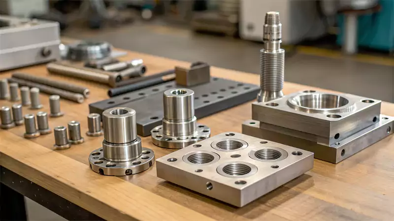
Manufacturing Capabilities That Matter in Practice
In real production, capability defines outcome. I have seen similar designs perform very differently depending on the supplier.
Precision investment casting stands out because it allows tight control over internal structure. At Allied Metal, we focus heavily on:
- Advanced wax pattern control for dimensional accuracy
- Vacuum casting and controlled atmosphere processes
- Optimized cooling curves to refine grain structure
- Integration with CNC machining for critical surfaces
This combination ensures both internal strength and external precision. It is especially important for aerospace, energy, and fluid control components where shear stress is a key factor.
Why Shear Stress Matters for Buyers of Custom Metal Parts?
I often speak with sourcing managers who focus on cost and lead time. That makes sense. But ignoring shear stress leads to bigger risks later.
Ignoring shear stress in custom parts can lead to premature failure, safety risks, and costly warranty issues, so buyers must evaluate suppliers based on engineering capability, process control, and material quality.
This is where technical understanding becomes a business decision. A small oversight can lead to major losses.
Risks of Ignoring Shear Stress in Custom Components
- Early component failure
- Increased maintenance cost
- Safety concerns in operation
I have seen projects delayed due to one failed part. The cost impact is often underestimated.
What Engineers and Procurement Teams Should Look For
From my experience, strong suppliers offer:
- Engineering support during design stage
- Stable and repeatable processes
- Clear quality control systems
This reduces risk before production even begins.
How Allied Metal Supports Shear-Critical Components
My journey started on the shop floor. I saw how process details affect real performance. That experience shaped how we build solutions today.
We combine precision investment casting with machining. This allows us to control both structure and tolerance. We support customers across Europe and the US, especially in applications where shear stress is critical.
When to Consult a Manufacturing Partner Early
Early involvement always helps. It allows better material selection, process planning, and cost control. It also prevents redesign later.
Conclusion
Shear stress is simple in form but critical in impact. When design, material structure, and manufacturing process work together, components achieve stable performance and long service life under real operating conditions.

-
A detailed overview of how we provide high-precision shaft manufacturing services for the automotive, medical, and industrial automation sectors. ↩
-
Learn why microstructure is crucial for material behavior beyond formulas, impacting real-world engineering outcomes. ↩
-
Learn why uneven grain structure compromises shear resistance and discover casting techniques that improve material performance and durability. ↩
-
Learn about the impact of residual stress on fatigue life and performance in CNC machining. ↩
-
Understand how smooth transitions reduce stress concentration and improve load distribution. ↩