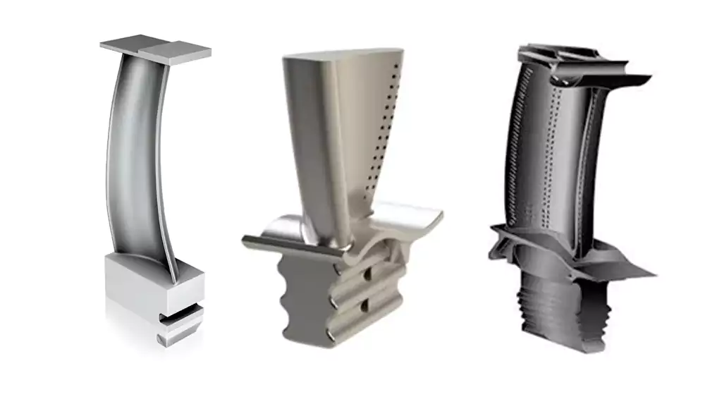
Complex turbine blade geometry looks impossible on paper. Thin walls warp. Curves distort. Internal channels shift. Many projects fail between design and production.
Investment casting enables complex turbine blade geometry by controlling metal flow, ceramic core stability, and shrinkage from the wax stage to solidification. When these three factors are managed together, thin walls, curved profiles, and internal cooling channels become repeatable, not risky.
I started my career pulling hot castings out of broken shells. The failed parts taught me more than the good ones. Over time, I learned that turbine blade geometry is not magic. It is behavior. Metal flows in patterns. Ceramic cores move if you let them. Once you understand both, the geometry becomes controllable.
For engineers evaluating suppliers for complex blades, I always recommend reviewing a complete overview of our custom turbine blade manufacturing capabilities to understand how geometry, materials, and post-processing come together in real production.
How Do We Engineer Thin Walls and Aerodynamic Curves Without Distortion?
Thin walls create anxiety. Curved surfaces increase risk. Engineers want performance. Foundries worry about scrap and deformation.
We achieve thin walls and complex curves by balancing alloy fluidity, shell strength, and shrinkage compensation at the tooling stage. Stable wax patterns and controlled filling prevent collapse and warping during solidification.
When I evaluate a turbine blade design, I first look at wall thickness distribution1. Most stainless and nickel alloys allow stable casting between 0.8 mm and 2.5 mm. Below 1.0 mm, metal flow becomes sensitive to temperature loss. Above 3.0 mm, uneven cooling creates internal stress. I avoid sudden thickness transitions. I prefer gradual steps or radiused blends.
In our dedicated investment casting for turbine blades process, I focus heavily on gating balance and thermal control because thin trailing edges are often the first area to fail if filling is unstable.
Thin-Wall Capability in Practice
Thin walls depend on three factors:
| Factor | What I Control | Why It Matters |
|---|---|---|
| Alloy selection | Pouring temperature and chemistry | Affects fluidity and fill distance |
| Shell strength | Slurry viscosity and stucco size | Prevents bulging or cracking |
| Gating design | Metal entry speed | Avoids turbulence and cold shuts |
I once worked on a turbocharger blade for a German client. The target wall thickness at the trailing edge was 0.9 mm. The material was GX5CrNiNb19-11. The blade length was 86 mm. The initial trials showed incomplete fill at the tip. I increased pouring temperature by 18°C. I modified the gate angle by 7 degrees. The next run achieved full fill with no visible cold shut. Final wall thickness tolerance was ±0.08 mm.
Curved and Freeform Geometry Control
Curved aerodynamic profiles depend on wax accuracy. I treat wax tooling as the real foundation. Shrinkage compensation must match alloy contraction. For most martensitic stainless grades, I apply 1.8% linear shrinkage allowance. For nickel-based alloys, I use 2.2% to 2.4%.
Uniform wall thickness helps reduce distortion. Sharp transitions increase stress concentration. I advise engineers to use minimum internal radii of 1.5 times wall thickness2. This reduces hot spots.
When external geometry is stable, machining only refines functional surfaces. Casting handles the complexity. CNC handles precision interfaces.
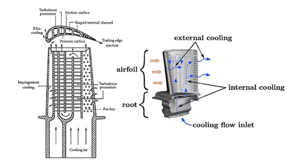
How Are Internal Cooling Channels Made Reliable?
Internal channels look impossible. Designers want narrow paths and long passages. They want maximum cooling and minimum weight.
We create internal cooling channels using ceramic cores that define the cavity during casting. Stability depends on core strength, positioning accuracy, and controlled metal pressure during filling.
I learned early that ceramic cores behave like fragile bones. If they move by 0.3 mm, the channel shifts. If they crack, scrap follows.
Ceramic Core Technology in Reality
I focus on three variables:
| Parameter | Typical Range | Risk if Ignored |
|---|---|---|
| Minimum channel diameter | 1.2–2.0 mm | Core breakage |
| Core length-to-diameter ratio | < 15:1 | Core bending |
| Core fixation points | ≥ 2 supports | Channel misalignment |
In one custom project, we produced a small industrial gas turbine blade with dual serpentine cooling channels.
Case Study: Custom Industrial Turbine Blade
| Parameter | Value |
|---|---|
| Material | Inconel 713C |
| Blade length | 112 mm |
| Minimum wall thickness | 1.1 mm |
| Smallest channel diameter | 1.5 mm |
| Channel length | 64 mm |
| Batch size | 600 pieces |
The first batch showed 0.4 mm channel offset at the tip. The cause was core float during pouring. I redesigned the core support with an additional ceramic bridge near the mid-span. The offset dropped to 0.08 mm. Scrap rate reduced from 18% to 3.5%.
Practical Manufacturing Limits
Long, narrow channels increase cleaning difficulty. Core removal requires controlled vibration and chemical leaching. Inspection also matters. I use X-ray testing3 for critical blades. Visual inspection is not enough.
The key lesson is simple. The geometry inside the blade looks impossible until you understand how ceramic cores4 behave and where metal wants to go. Once you control those two factors, internal complexity becomes stable.
What Are the Real Manufacturing Boundaries Engineers Should Respect?
Simulation looks perfect. Reality looks different. Many designs pass digital checks but fail on the floor.
Investment casting has limits defined by metal flow, thermal stress, and core stability. Designs that ignore these limits lead to warping, incomplete fill, and channel misalignment.
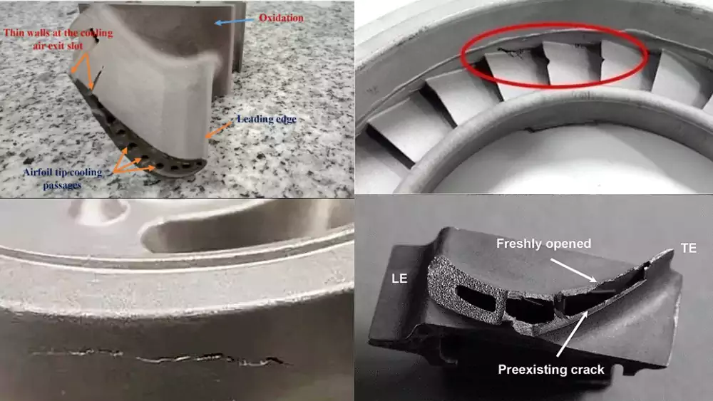
I have seen thin walls collapse because engineers pushed below safe thickness. I have seen shells crack because feeding was not balanced.
Where Simulation and Production Differ
Simulation predicts flow. It does not always predict shell strength variation. Thermal stress accumulates during solidification. Large flat areas warp if cooling is uneven.
Common Thin Wall Failures
| Failure Mode | Root Cause | Prevention |
|---|---|---|
| Cold shut | Low temperature | Optimize gating |
| Local collapse | Weak shell | Increase shell thickness |
| Warping | Uneven cooling | Improve riser placement |
Internal Channel Risks
Core shift creates eccentric channels. Excessive channel length causes bending. Tight tolerances without machining allowance create rejection.
I often tell engineers to leave machining allowance on datum surfaces. I recommend at least 0.5 mm for critical interfaces. Casting achieves near-net shape, not final tolerance for high-load fits.
When engineers respect boundaries, success becomes predictable.
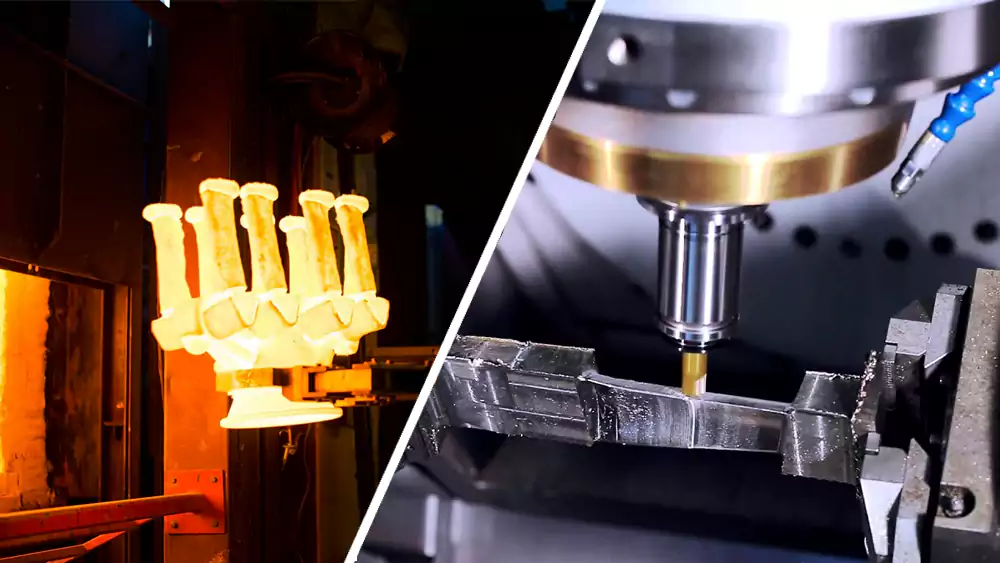
When Should We Combine Investment Casting with Precision Machining?
Casting alone does not finish a turbine blade. Machining completes function. The balance defines cost and performance.
We cast complex geometry such as curved profiles and internal channels, then machine functional surfaces like bearing seats and alignment holes to achieve final tolerance and performance.
I divide features into two groups.
Features Best Cast
- External aerodynamic contours
- Internal cooling passages
- Complex twisted profiles
Features Best Machined
- Mounting faces
- Axial bores
- Balance-critical zones
If we machine too much, cost rises fast. If we cast too close to final tolerance, risk increases. I aim for balance. For medium batch sizes above 300 pieces, investment casting provides cost stability. For very low volume prototypes, hybrid machining may be better.
For engineers comparing manufacturing routes, I also explain the trade-offs in detail in this guide on investment casting vs CNC machining for turbine blades, where I break down cost, geometry freedom, and scalability.
I started on the foundry floor. I learned from broken shells and rejected parts. After twenty years, I know this: turbine blade geometry is not about chasing extremes. It is about understanding metal behavior and respecting process limits.
Conclusion
Complex turbine blade geometry becomes achievable when thin walls, ceramic cores, and machining strategy work together under controlled manufacturing limits.

-
Understanding wall thickness distribution is crucial for ensuring casting stability and avoiding defects in turbine blades. ↩
-
Using minimum internal radii reduces stress concentration and hot spots, improving blade durability and performance. ↩
-
Learn why X-ray testing is crucial for detecting internal defects that visual inspection misses, ensuring higher blade reliability. ↩
-
The Role and Types of Ceramic Cores in Aerospace Applications. ↩