Many turbine blade designs look perfect in CAD. But they fail in real production. I have seen this happen too often on the shop floor.
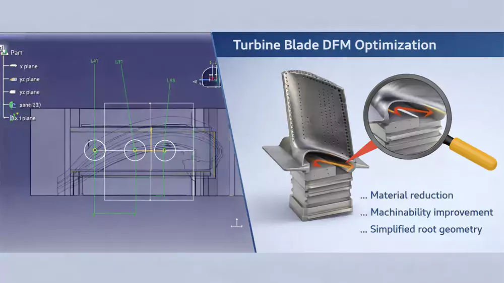
Design for Manufacturing (DFM) for turbine blades means designing parts that can be reliably cast, machined, and inspected with stable quality, low scrap rates, and controlled cost. Turbine blades are more complex due to high-temperature alloys, curved geometries, and combined casting and CNC processes.
Many turbine blade designs work in CAD—but fail in real manufacturing. I have seen this many times. Let me show you why this happens and how to avoid it.
What Is Design for Manufacturing (DFM) for Turbine Blades?
Most engineers focus on performance first. That is normal. But when manufacturing is ignored, problems show up fast.
DFM for turbine blades means optimizing geometry, material selection, and tolerances so the part can be produced consistently through investment casting and CNC machining without defects or excessive cost.
I often tell clients this simple truth. A design is only successful if it can be produced at scale. If not, it is just a concept.
Why turbine blades are more difficult
Turbine blades combine several challenges:
- High-performance alloys like nickel-based materials
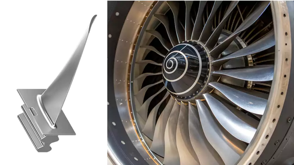
- Complex aerodynamic surfaces
- Internal cooling structures
In many cases, these parts rely on investment casting for turbine blades combined with machining. That adds another layer of complexity.
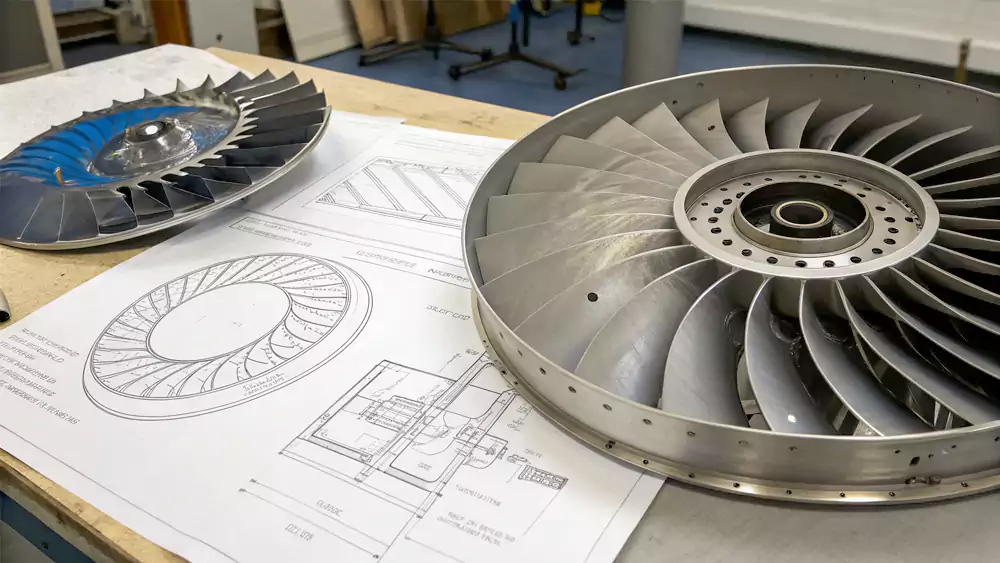
Where design meets reality
I receive CAD files every week. Many look perfect. But I can already see risks:
- Thin trailing edges1
- Unstable internal cores
- Sharp geometry transitions
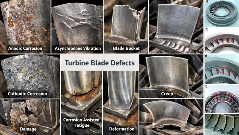
These issues are not always visible in simulation. But they appear quickly in production.
5 Costly Turbine Blade Design Mistakes Engineers Must Avoid?
Small design details can destroy yield. I have seen scrap rates go above 60% because of simple mistakes.
The most common turbine blade DFM mistakes are thin wall sections, unmanufacturable internal cooling features, sharp transitions, overly tight tolerances, and ignoring material behavior during casting and heat treatment.
If you are working on custom turbine blade manufacturing, these are the risks you must control early.
1. Thin wall sections2
- Problem: Metal flow becomes unstable
- Result: Misruns or distortion
- Fix: Increase thickness or redesign flow
2. Complex internal cooling channels3
- Problem: Ceramic cores shift or break
- Result: Blocked passages or scrap
- Fix: Simplify channel layout
Designing complex geometry is possible, but only if it matches what casting can achieve. This is why I always refer to how investment casting enables complex turbine blade geometry.
3. Sharp corners and transitions
- Problem: Stress concentration
- Result: Cracks during cooling
- Fix: Add fillets and smooth curves
4. Overly tight tolerances4
- Problem: Excess machining effort
- Result: High cost and rejection rate
- Fix: Apply tolerances only where needed
You can learn more about realistic tolerance limits in CNC machining tolerances for turbine blades.
5. Ignoring material behavior
- Problem: Shrinkage and deformation not considered
- Result: Dimensional failure
- Fix: Design based on alloy behavior
Material choice matters more than most engineers expect. Especially when using nickel-based superalloys for turbine blades.
Real case from my shop
I worked on a turbine blade project with the following data:
| Parameter | Value |
|---|---|
| Material | Inconel 738 |
| Blade length | 185 mm |
| Min wall thickness (original) | 0.6 mm |
| Cooling channels | 6 |
| Scrap rate (initial) | 68% |
Problems:
- Thin trailing edge
- Core instability
Solutions:
- Increased thickness to 1.1 mm
- Simplified channel intersections
| Result | After Optimization |
|---|---|
| Scrap rate | 12% |
| Lead time | -25% |
| Cost per part | -18% |
This is why I always push DFM early. It saves time, cost, and frustration.
Why Some Turbine Blade Designs Fail in Production (Even If CAD Looks Perfect)?
Many engineers trust CAD results too much. I understand that. But production is different.
Turbine blade designs fail in production because CAD does not fully account for metal flow, thermal stress, tooling limits, and process variation in casting and machining.
Let me show you the gap clearly.
CAD vs factory reality
| Design | In CAD | In Factory | Fix |
|---|---|---|---|
| Thin trailing edge | OK | Warping | Increase thickness |
| Complex channels | OK | Core failure | Simplify |
| Sharp corners | OK | Cracks | Add fillets |
Why this gap exists
CAD focuses on geometry. Manufacturing depends on physics:
- Metal flow is not uniform5
- Cooling creates stress
- Tools have access limits
In many projects, I also need to consider follow-up steps like secondary operations for turbine blades. These steps can fail if the design is not DFM-ready.
Transition to solution
At this point, most engineers realize one thing. Design alone is not enough. You need a manufacturing-first mindset. Let me show you how I approach this in real projects.
How to Optimize Your Turbine Blade Design for Manufacturing (DFM Checklist + Expert Support)?
Most manufacturing issues can be avoided early. I use a simple checklist in every project.
To optimize turbine blade manufacturability, maintain uniform wall thickness, simplify geometry, allow machining stock, design for casting flow, and ensure all features can be inspected.
If you are unsure about material choice, it is worth understanding how material selection impacts turbine blade lifespan and cost.
Practical DFM checklist
- Maintain uniform wall thickness
- Avoid sudden geometry changes
- Design for smooth metal flow
- Add machining allowance
- Ensure inspectability
How I support clients
I review every design before quotation. This is part of how I reduce risk.
- 20+ years in casting and machining
- DFM review before tooling
- One-stop solution
In many cases, I also help clients decide between processes like casting and machining. If you are unsure, this comparison of investment casting vs CNC machining for turbine blades can help.
What happens next
In a real project, I do this:
- Identify risk areas
- Suggest design changes
- Estimate cost impact
- Confirm manufacturability
Final transition
If you wait until production, it is already too late. DFM must happen early. That is where the biggest savings come from.
Upload your turbine blade drawings and get a manufacturability review within 24 hours.
Conclusion
Good turbine blade design must match real manufacturing conditions. That is the only way to reduce scrap, control cost, and ensure performance.

-
Learn about the production risks thin trailing edges pose and how to address them for successful turbine blade manufacturing. ↩
-
Explore this link to understand how thin wall sections affect metal flow and how to fix issues like misruns or distortion. ↩
-
Learn why simplifying cooling channel layouts prevents ceramic core issues and reduces scrap rates. ↩
-
Discover how applying realistic tolerances can reduce machining effort, cost, and rejection rates. ↩
-
Understanding metal flow helps improve casting quality by addressing common defects caused during manufacturing. ↩