Many engineers ask for ±0.01 mm on every surface. Then cost rises, scrap rises, and lead time slips. The part looks precise on paper. The project suffers in reality.
For custom turbine blades, ±0.02–0.03 mm is the realistic range for most functional features. ±0.01 mm is possible on selected areas, but it increases scrap rate, inspection time, and machining cost very quickly.
I have worked on turbine blades for over twenty years. I started on the shop floor. I learned by making mistakes and fixing them. In our daily work at Allied Metal, especially in our custom turbine blade manufacturing projects, I review tolerances before I ever review price. I will explain what is realistic, what drives cost, and how I set tolerances with customers before production.
What CNC Tolerances Are Realistic for Custom Turbine Blades?
Many buyers assume tighter is safer. In reality, tighter is not always better. Turbine blades behave differently from simple shafts or blocks.
For most custom turbine blades, ±0.02–0.03 mm is achievable and stable in production. ±0.01 mm can be controlled on key datum or sealing surfaces, but not as a blanket requirement.
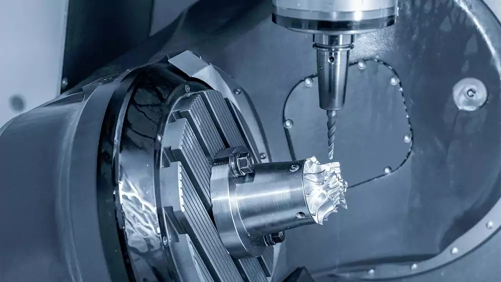
5-Axis Machining After Investment Casting
I often machine blades after casting. Casting gives near-net shape. CNC defines the critical surfaces. If you want to understand the base process, I explain it in detail in our guide on investment casting for turbine blades.
In this setup, I usually control:
- Datum faces1: ±0.02 mm
- Mounting holes position: ±0.02 mm
- Airfoil profile: ±0.03 mm
Profile tolerance is not the same as size tolerance. A ±0.02 mm thickness control is easier than a 0.02 mm total profile on a twisted airfoil. Profile control depends on tool path, tool wear, and machine stability.
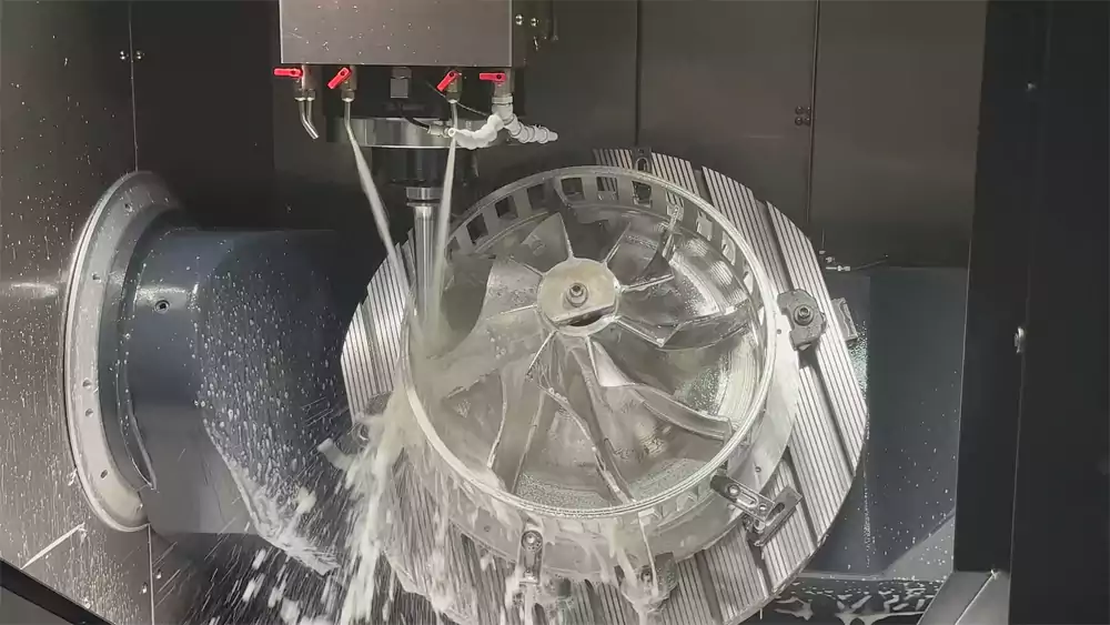
Solid Billet Machining
When I machine from solid billet, I remove much more material. Heat builds up. Internal stress releases. That is why I often compare both routes in our article about investment casting vs CNC machining for turbine blades.
Material matters:
| Material | Typical Stable Tolerance | Main Risk |
|---|---|---|
| Aluminum | ±0.02 mm | Low stress |
| Stainless Steel | ±0.02–0.03 mm | Tool wear |
| Inconel 7182 | ±0.03 mm | Heat and distortion |
Inconel moves more. It resists cutting. Tool wear changes size. I must measure more often.
Small Batch vs Medium Batch
In small batches, I can fine-tune offsets part by part. In medium batches, consistency matters more than extreme tightness. Statistical variation appears. A ±0.01 mm requirement leaves almost no room for normal process spread.
I always tell customers this. Stable production matters more than a single perfect sample.
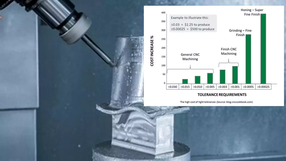
When Tight Tolerances Stop Being Engineering and Start Driving Cost?
Many drawings tighten tolerance step by step. Cost does not rise step by step. Cost jumps.
When tolerance moves from ±0.03 mm to ±0.02 mm, cost rises moderately. When it moves to ±0.01 mm, cost and risk rise sharply due to scrap, extra inspection, and machine control time.
The Cost Curve in Real Production
I have seen this pattern many times:
| Tolerance Level | Relative Machining Cost | Scrap Risk | Inspection Effort |
|---|---|---|---|
| ±0.05 mm | 1.0x | Low | Standard sampling |
| ±0.03 mm | 1.2x | Low | Normal CMM check |
| ±0.02 mm | 1.4x | Medium | Increased checks |
| ±0.01 mm | 2.0x–2.5x | High | Full CMM, repeated |
When I target ±0.01 mm, I reduce feed. I change tools more often. I let the machine warm up longer. I measure every few pieces. All of this adds time.
Heat Treatment and Secondary Machining
If the blade needs solution treatment or aging, distortion appears. Even 0.02 mm warp can break a ±0.01 mm spec. Then I must re-clamp and re-machine. That adds cost and risk.
Case Study: Custom Turbocharger Turbine Blade
A German customer once ordered a custom turbocharger turbine blade for a prototype program.
Project Data
| Parameter | Value |
|---|---|
| Material | Inconel 713C |
| Overall Height | 62.5 mm |
| Blade Count | 11 |
| Required Airfoil Profile | 0.02 mm |
| Mounting Bore Tolerance | ±0.015 mm |
| Heat Treatment | Solution + Aging |
| Batch Size | 80 pcs |
At first, the drawing required ±0.01 mm on all machined surfaces. I reviewed the function with their engineer.
We adjusted tolerances:
- Bore: ±0.015 mm
- Back face: ±0.02 mm
- Airfoil: 0.02 mm profile
- Non-critical chamfers: ±0.05 mm
Result After Optimization
| Metric | Before (Estimated) | After (Actual) |
|---|---|---|
| Scrap Rate | 18% | 4% |
| Lead Time | 10 weeks | 8 weeks |
| Machining Cost | Baseline 100% | 78% |
| Functional Test | Pass | Pass |
Performance testing showed no loss in efficiency. This is the difference between chasing numbers and controlling function.
Common Over-Specification in Turbine Blade Drawings?
I often see drawings that copy old aerospace standards without review. That causes problems.
Over-specification happens when every surface carries the same tight tolerance, even when only a few features affect function. This increases cost without improving performance.
All Surfaces at ±0.01 mm
Some drawings mark ±0.01 mm in the title block. That means every edge, chamfer, and non-critical surface follows that rule. This makes no sense for many industrial applications.
A leading edge radius may affect flow. A small backside chamfer does not.
No Separation of Functional and Non-Functional Surfaces
I divide features into:
- Functional surfaces
- Assembly reference surfaces
- Cosmetic or secondary features
If all receive the same tolerance, cost rises with no gain.
Profile Tolerance Misuse
Profile tolerance controls the whole 3D surface. On a twisted blade, 0.01 mm profile across the entire airfoil is extremely demanding. In many cases, complex geometry is better controlled at the casting stage. I explain this in our article about how investment casting enables complex turbine blade geometry.
Engineering is about function. It is not about writing the smallest number.
A Machinist’s Practical Approach to Setting the Right Tolerance?
Many suppliers accept the drawing and quote directly. I do not work that way. I review first.
A good supplier questions tolerances, identifies critical features, and aligns machining strategy with function before final quotation.
Step 1: Identify Critical Features
I ask simple questions:
- Which surface controls assembly fit?
- Which feature affects balance?
- Which area affects flow or sealing?
I mark these as priority control features.
Step 2: Assign Tiered Tolerances
I suggest a layered structure:
| Feature Type | Suggested Tolerance |
|---|---|
| Datum / Mounting Bore | ±0.015–0.02 mm |
| Back Face | ±0.02 mm |
| Airfoil Profile | 0.02–0.03 mm |
| Chamfers / Non-critical | ±0.05 mm |
This keeps cost stable. It protects function.
Step 3: Align Process With Tolerance
If tolerance is tight, I adjust:
- Dedicated fixture design
- Controlled tool life
- Warm-up cycle
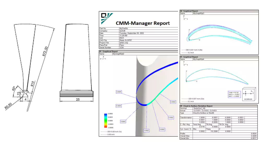
- CMM inspection plan3
I explain this before production. I want sourcing managers and quality managers to see the full logic. Many of my European customers care about documentation and repeatability. I respect that. I provide measurement reports, process flow charts, and inspection records that match the agreed tolerance plan.
Precision is not about showing the smallest number. It is about delivering repeatable blades that work inside real machines.
Conclusion
For custom turbine blades, ±0.02–0.03 mm is the practical balance. Real engineering focuses on function, stability, and controlled cost, not the smallest number on the drawing.

-
Explore this link to learn how precise control of datum faces ensures accuracy in machining critical components. ↩
-
Discover expert tips on managing heat, distortion, and tool wear when machining Inconel 718 for better results. ↩
-
Learn why implementing a CMM inspection plan is crucial for ensuring repeatable and accurate measurements in production. ↩